
Many users have a fear UV mapping, assuming a degree in black magic or voodoo is necessary to produce useful results. Fortunately, nothing is further from the truth. The basic concept is easy; UV mapping is simply the process of translating a 3D surface with volume and shape onto a flat 2D texture image. An easy way to visualize how that works is to imagine the object was accurately wrapped in gift wrap, and the UV map is the careful unwrapping of the object pressed flat, much like a geographical map of the earth, which suffers from the same constraints as a UV map. While it might be easy enough to understand, it's the actual execution of the process that requires a little science and whole lot of art, but like modeling, or texturing or even rendering, understanding the tools is an important part of understanding the process. MODO provides an flexible range of functions that simplifies the process, making what many consider a tedious task a lot less painful, and possibly even enjoyable. As they say, practice makes perfect.
Understanding UVs
UV map values are simply position coordinate on a 2D texture stored within an associated vertex. In MODO, this is a float value, meaning it is a number defined by a decimal point, chosen for the precision it provides. The UV Map viewport plots those 2D position values on a grid, including the edges and polygons, so its easier to reference how the 2D geometry map relates to its 3D counterpart. These values are typically confined to the 0-1 area of the grid as this is the normal space (or home) position of the texture; any texture applied using a UV map will always fill the entire 0-1 space; any part outside of this area will simply repeat the texture (how it gets tiled is controlled by the Texture Locator). By confining the map values within this single quadrant, it is easy for users to control positioning, avoiding any overlapping if necessary, as this causes errors when baking textures. By scaling UV values larger than the 0-1 space, user can precisely control the tiling of the image on the surface. There are no specific contraints regarding the position of geometry within UV space.
One major point of confusion is the shape of the UV editing viewport and how it relates to the image aspect ratio. The UV window is square, so naturally users assume UV mapped images need to be square as well, but this is not the case at all. Images can be any size, any aspect ratio and any resolution, it will still always map to the 0-1 space of the UV grid. For very wide image or very tall, the values are positioned proportionately across the texture, which is why it can be advantageous to think of the values as percentages, a float value of .5 is effectively the 50% position, and will position a vertex directly in the center of the image, regardless of the images size or shape. It is that fact alone that makes UV mapping so precise and valuable. When displaying non-square images in the UV viewport, the image will simply be distorted to fill the 0-1 space. Users can also enable the 'Use Aspect Ratio' in the viewports options to distord the UV space view, in turn displaying the image aspect properly.
Making UV maps
For many instances, the texture projection modes of the 'Texture Locator' provide plenty of control for applying texture layers to a surface. UV maps are only necessary for surfaces that require high precision texture mapping such as for organic characters, applying a logo to a bottle in a specific way, or if the model has a peculiar shape. They are also a requirement of any real-time game engine and object to object baking. If there is no intention of applying a texture layer to your surface, then a UV map is unnecessary.
Generating and editing maps take place in the UV editing tab of the main (default) interface. This is where the dedicated UV editing viewport is located along with quick access to the most often used tools and commands. When working in the UV viewport, virtually all the same tools, modes and functions used in the 3D viewports apply; transform tools, modeling tools, even sculpting tools can be utilized to edit maps. Most operate the same as they do in any other viewport, but some tools will behave slightly differently. For instance, regardless of the geometric topology, function like 'Select Connected' will only select the connected area of a UV island when applied to the UV view, MODO tools are just smart that way
To start making UVs, user would need to first select or define a vertex map to store values into. UVs are just another type of vertex map, managed within the Lists viewport whose use is covered on the Vertex Maps page of the documentation. Once the proper map type is selected in the Lists viewport, users can select the polygons they wish to map and invoke any of the tools or commands. For interactive tools such as Unwrap, users can haul directly in the 3D viewport, and see real time updates of the UV map generation in the UV viewport.
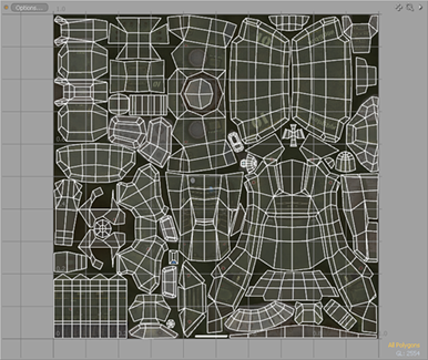
The tool or process used to produce the map is largely dependent on the shape of the surface. Geometric shapes, like a can of soda, or a box, will do best with the Projection tool, which generates UV values using options similar to those found in the texture locator, such as 'Spherical', and 'Planar'. For organic shapes, the Unwrap tool can produce great results right away, making what was once a tedious process, easy. Long, winding object (like a belt) can leverage the Peeler tools ability to produce precise maps with uniform spacing. Often times, the result produced by a given tool will be adequate and users can move to other tasks. Other times, the result will simply provide a starting point for further refinement. This can be the case for the default values generated by MODO's primitive geometry. Depending on application, the default map may not be appropriate or optimum for the intended use. Lets take a look at a basic example in this video--
As illustrated here, the layout of the map itself is largely dependant on how the geometry will be used, and there's no reason why users shouldn't set things up to make surfacing easy. It should also be comforting to know, there are no set rules to follow for layouts. Users can position UV islands, (grouped areas of geometry in a UV map) anywhere they wish in the UV map. It can help to keep in mind some guidelines, these are not hard and fast rules, but can be helpful to consider when creating a map.
Minimize Seams
Seams are the edges, or breaks in geometry between UV islands and are inevitable for nearly every model. Sometimes they can cause issue with painting or image based Sculpting. If at all possible, its best to define seams in inconspicuous places. For human characters, this can be the inseam of the legs and thighs, under the arms, and behind the head and down the back. When viewed form the front, most of these seams would be hidden from view. When seams can't be hidden from view, image commands like 'Expand UV Border' can be useful in minimizing their appearance. It might seem obvious, but it should be said that having as few islands as necessary will reduce seams, so keep them to the minimum.
Managing Distortions
Two main goals when UV mapping are to eliminate or reduce seams, and to also minimize distortion from stretching. Unfortunately, these two are not mutually exclusive. Distortion is a fact of life with UV mapping. Completely eliminating distortion would require an increase in UV seams. Fortunately, MODO has a number of tools and functions to help users manage distortion. First off, users should enable the 'Show Distortions' option of the UV view, this produces a color overlay on the geometry that signifys the amount a polygon is distorted, as to say scaled or stretched in relation to neighboring polygons. Polygons that are the closest relative size to others in the map with the least distortion will display a middle gray/green color. Distorted and smaller relative polygons will fade toward red, while distorted and larger relative polygons will display blue. Users can also display the distortion colors in the 3D viewport by selecting the 'Vertex Map' viewport style and then selecting the UV Distortion named vertex map generated under the 'Other Maps' heading of the vertex map list viewport. Once users can see where the problem areas are, they can take action to minimize issues. The UV Relax tool is the number one option for reducing distortions. Users can use it to massage a map, exactly as the namesake suggest, by relaxing the data, tugging and pulling neighboring polygons until a comfortable medium can be acheived. Users can limit the application of the relax using falloffs as well.
Consistent Texture Density
For the most part, models will look their best when an image maps pixel density is spread evenly across the surface. Take for instance a sphere, an image map would need to be twice as wide as it is high for even pixel density, because the circumference is twice the distance of how far the image wraps from top to bottom. This also means to compact UV islands as closely as possible to get the most out of the number of pixels in the image, large gaps between islands waste precious texture space. Quite often, professionals will map a temporary grid or checkerboard pattern onto the object to get direct visual feedback of how consistent the textures density is. There is a UV Check image included in the content download in the "Materials > Miscellaneous" folder.
Take the Image Map into Account
It's important to consider the texture map(s) that will be applied to the surface using the UV map. What will its size and aspect ratio be? Say if you were UV mapping a rectangular sign that was much wider than it was high. It would be far easier to make the final image the proper size and aspect ratio, especially if it needed further editing down the road (as opposed to artificially squeezing it in an image editor). In both these cases the geometry would appear squashed while displayed in the square UV viewport, but it will render exactly as expected.
Is Orientation Important
In most cases, orientation of individual islands is arbitrary, but in some cases it can become important. For example, when texturing a face directly in 3D, the paint tools take care of projecting the pixels into the image properly, so the UVs position within the map is inconsequential. But, if it becomes necessary to make further edits say in Photoshop, it will be far easier to accomplish when the face is straight up and down instead of at some odd angle.
Overlapping UVs
Overlapping UVs aren't always a bad thing. There are some instances when overlaps are OK such as when each overlapping part has a different material tag; this simplifies the model by reducing the total number of vertex maps. Barycentric maps (where each individual polygons is mapped to the entire 0-1 UV space) are useful in controlling the tiling of images. While texture memory in games continues to go up, it was a good idea to model and texture half of a character and then mirror it (making UV overlaps) effectively doubling the texture resolution, while halving the image size. When baking textures out, overlapping UVs will cause errors, so in those cases, avoid them.
Get to know the tools
MODO has a huge toolbox, especially in the vertex mapping arena, and if you aren't at lease familiar with what it has to offer, you might be limiting yourself to what can be accomplished. This documentation is a great way to familiarize yourself with what MODO has to offer, providing you the best leverage to get out of difficult situations. The functional operation of the individual tools is covered within each tools respective documentation page.
Applying the Map
UV maps are mainly employed when applying textures, so once the map has been created, it will first show up in the Vertex Maps window under the UV Maps section. To actually utilize the map itself, one would need to first apply a texture layer, either as an 'Image Map' or a 'Procedural' texture. Once applied, users can access the associated 'Texture Locator' from the 'Item List', or the 'Shader Tree' (by LMB+clicking the ' + ' icon preceding the layer name). Within the locators properties, there is a setting 'Projection Type', when choosing the option 'UV Map', users may select the specific map from the selector below. MODO will try to automatically select the proper map when applying an image map to any geometry that contains a UV, but it may be necessary at times to specify alternate maps when MODO chooses incorrectly.
UV maps are also useful in the application of Anisotropic shading (which can be further controlled by an image map). When a map is applied, the 'U' horizontal direction (of U and V) defines the length that the anisotropic shading will follow. The particular map can be specified whenever the 'Anisotropy' setting of the Material item is set above 0%.
Lastly, UV maps can be leveraged to simplify certain modeling tasks. Often times it is easier to apply a UV maps to geometry, acting as a visual aid, the map can then be converted to a vertex map of another type, such as a weight map and applied as a falloff. One quick example is the possibility of using the Peeler option on a spiral. This creates a linear type uv that follows the contours of the form. Converting this to a weight map using the Math tool. Then applying the resulting weight as a falloff to the Push tool, allowing the interactive scaling of the spiral along its length.

TIP: Discontinuous vertices in a UV map are those that are single vertices within the model, but have two locations in a UV map (from a shared edge that are split into separate UV islands) MODO highlights discontinuous vertices and edges in the UV viewport as a light lavender color to make it easier to locate the associated vertex or edge.

