
The UV viewport is much like the 3D OpenGL Viewport, only instead of representing 3D space, it shows users the two dimensional view of UV space. UV maps are the flat 2D representations of a model's 3D surface for the application of texture maps (images). Users not familiar with what a UV map is can explore them further on the Working with UV maps page of the MODO tools documentation. The main toolbox and viewport for UV mapping is available in the default 'UV' edit interface. If this Tab is not visible, users may select the UV interface using the "Layout > Layouts > UV Editor" menu command.
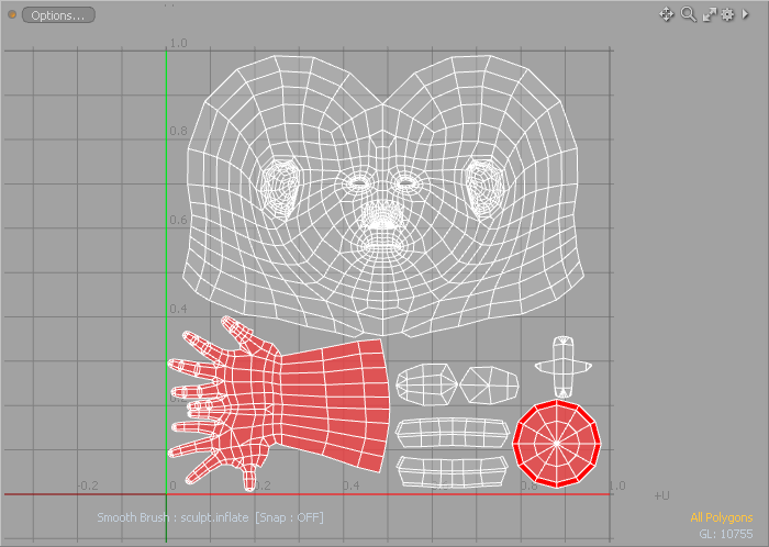
Compared to the 3D viewport, the UV viewport itself is rather sparse. The 3D grid is replaced by the 2D UV grid and flat background color. Relevant on-screen information overlays are still located toward the bottom of the viewport. The 'Thumb' and 'Widget' viewport controls are still available toward the top, covered on the 'Layout Controls' page of the documentation. The pan and zoom navigation widgets are located in the upper right corner, users can LMB+click on these icons to move and scale the contents of the viewport, making it easier to see certain areas for detailed editing. Lastly, user can LMB+click the 'Options' capsule shaped button toward the upper left corner to open a context menu with a variety of viewport customizing controls, acting as common shortcuts for the same options available in the viewport Properties panel.
Navigation
Navigation of the UV view is very similar to the 3D views. Users can use the zoom and pan widgets to navigate, but most will find it far easier to use the mouse and keyboard combinations MODO provides.
Ctrl+Alt+LMB = Zoom to mouse position
Alt+LMB = Pan view
Mouse Wheel =
Zoom to mouse position
Shift+Alt+MMB = Pan Horizontally (U direction)
Shift+Alt+RMB = Pan Vertically (V direction)
Ctrl+Alt+RMB = Box Zoom (drag to define zoom area)
A = Zoom to geometry extents
Shift+A = Zoom to selection
'.' & ',' = zoom in & out (easier to think of < and > key)
G = Center current mouse position
Visibility
MODO provides a way for users to modify the visibility of object in the viewport directly. While generally users can toggle visibility of items in the Items list, that changes visibility of the entire layer. These commands allow the temporary toggling of visibility of only the selected element, including components, dependent on the selection mode. Once hidden, geometry will be un-editable, meaning it cannot be selected or moved. To apply, simply select the geometry component you wish to hide and invoke the menu bar command "View > Hide Selected" or press the 'H' key. To make the geometry visible again, invoke the "View > Unhide" command or press the 'U' key. When a file is saved and re-opened later, all hidden polygons will be visible.
H = Hide Selected (Hides all if nothing is explicitly selected)
Shift+H = Hide Unselected
(Hides all the unselected Geometry)
Ctrl+H = Hide Invert (Toggles visibility, inverting the present state)
U = Unhide (Makes all hidden geometry visible)
Locking
Providing a similar
function to hiding, Locking allows users to fix a selection of geometry so that is is immovable and unselectable, effectively un-editable, however it will still be fully visible. Unlike hiding, this locking function is limited to the component selection modes. To apply, simply select some geometry, and invoke the menu bar command "Edit > Lock Selected" or press the 'J' keyboard shortcut. Users can unlock any locked elements in an item layer with the "Edit . Unlock" command or by pressing 'I'.
J = Lock Selected (Locks all if nothing is explicitly selected)
Shift+J = Lock Unselected (Lock all of the unselected geometry)
Ctrl+J = Lock Invert (Toggles locked state of all geometry)
I = Unlock (Makes all locked geometry editable)
Viewport Options
Users can select from a variety of display customizing options from the viewport Properties menu, found by clicking the gear icon in the upper right corner, or by holding the mouse pointer over the viewport and pressing the 'O' key. Acting as a standard dialog, edits can be made normally. As soon as the mouse pointer moves clicks away from the menu, it will disappear. Many of these display options are also available using the 'Option' context menu button in the upper left of the viewport.
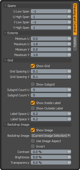 Spans--
U/V High/Low Spans: Users can control the number of UV sections or spans displayed in the viewport using these controls. Each span represents a complete UV grid section. The default value produce the grid found most commonly in 3D programs representing, the -1 to 1 UV space coordinates. Users can place vertex data anywhere within UV space, this option simply determines the display extent of the UV grid.
Extents--
Minimum/Maximum U/V: Users can control the active area for UV mapping using the extents options.
Grid--
Show Grid: This toggle determines the visibility of the UV grid in the viewport.
Grid Spacing U/V: Users can set the grid line spacing using these values, defined as decimals of the UV unit. The default value of 0.1 draws grid lines every 10th of a unit.
Show Subgrid: For detailed maps, the standard grid may not have enough subdivisions to be visible when zoomed in, users can enable this setting to display a lighter secondary grid.
Subgrid Count U/V: These options determine the number of divisions between each 'Grid' subdivision.
Show Inside Label: This option toggles the visibility of grid value labels inside the grid area.
Show Outside Label: This option toggles the visibility of grid value labels outside the grid area.
Label Space U/V: These values determine the division level for the grid labels. Typically this value will match or be a division of the 'Grid Spacing' value.
Backdrop Image--
Show Image: This option allows users to toggle the visibility of a background reference image map. The particular image displayed is determined by the 'Backdrop Image' settings.
Backdrop Image: The 'Backdrop Image' option offers users the ability to select from a list of loaded images (those that are available in the Clips/Image list) or when the option is set as "Current Image Selection", whatever the current image selected. Images can be selected in the 'Images' tab or within the 'Shader Tree'.
Use Image Aspect: It is a common misconception that UV mapped images need to be square (with equal height and width). Regardless of aspect or resolution, images will render and display correctly. When users enable the 'Use Image Aspect' option, the UV window will be scaled horizontally to math the aspect ratio of the selected image making it easier for users to edit UV maps for non square aspect ratios.
Invert: This command will simply invert the RGB color values of the Backdrop Image producing a negative effect.
Contrast: Contrast is the apparent visual different between light and dark values in an image. Values greater than 0% will increase the contrast of the backdrop image, while values lower than 0% will decrease it.
Brightness: Brightness is the degree or amount of light or luminosity in an image. Values greater than 0% will increase the brightness of the backdrop image, while values lower than 0% will decrease it.
Transparency: Transparency determines the opacity of the backdrop image. Values greater than 0% will increase the transparency, ramping toward 100% where the image would become completely invisible.
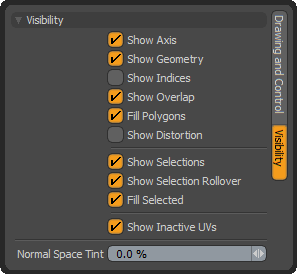 Visibility--
Show Axis: This option toggles visibility of the colored axis display at the UV origin.
Show Geometry: This option toggles visibility of all geometry in the viewport.
Show Indices: This option toggles visibility of vertex index value for selected items.
Show Overlap: When the area of a polygon sits over the area of another, enabling this option will display a red highlighting to signal users of the overlapping state. Users will want to avoid overlapping when baking as it will cause rendering errors, but often times for texturing game models it is desirable.
Fill Polygons: This option toggles visibility of the faint fill coloring given to polygon faces.
Show Distortion: Two main goals when UV mapping are to eliminate or reduce seams, and to also minimize distortion from stretching. Unfortunately, these two are not mutually exclusive. Distortion is a fact of life with UV mapping. Enabling this option will display a color overlay on the geometry fading toward red when polygons are distorted and smaller relative to other polygons in the map, and fading toward blue when they are distorted and larger relative to other polygons. Polygons that are the closest relative size to others in the map with the least distortion will display a middle gray/green color. Users can also display the distortion colors in the 3D viewport by selecting the 'Vertex Map' viewport style and then selecting the 'UV Distortion' named vertex map generated under the 'Other Maps' heading of the vertex map 'Lists' viewport.
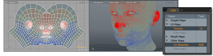
When 'Show Distortions' is enabled, colors overlay onto the geometry signifying distorted areas of the UV map.
Show Selections: This option toggles visibility of highlighted polygon selections, by default an orange color.
Show Selection Rollovers: This option toggles visibility of selection rollover pre-highlighting.
Fill Selected: This option toggles visibility of the orange fill color for selected polygons.
Show Inactive UVs: This option toggles the visiblity of UV maps for Items in the background (visible but not selected in the Items list).
Normal Space Tint: The 'Normal Space Tint' option controls the amount of tint coloration applied to the Normal Space area of the UV viewport, identifying the central or main UV area of 0 to 1. This is where textures originate, outside of this area the texture simply tiles.

