
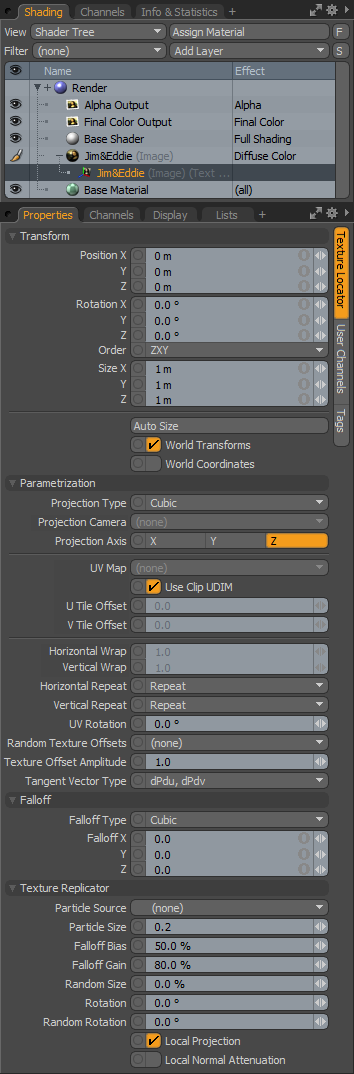
When any texture layer is created in the Shader Tree, image based or procedural, an associated 'Texture Locator' item is automatically generated and added to the items list and linked by the texture layers 'Locator' property. By default, Texture Locators are generally added to a folder (really a group locator item) called 'Texture Group'. This makes it easy to toggle the visibility of the locators in the 3D viewports, as some users find them distracting. Users may select the texture locator directly in the items list, or by selecting the locator icon in any 3D viewport. Most often though, users will select them via the shader tree; when any texture layer is selected in the tree, the locator is available in the named subtab on the right side of the items associated 'Properties' panel. Additionally, the locator may be toggled by the small '+' sign preceding the texture layers name in the Shader Tree, LMB+clicking the '+' icon reveals the layer.
Texture locators provide a very important function as they control the application of the texture layer over the rendered surface. A Texture Locator is like a regular 'Locator' Item, in that it has Position, Rotation and Scale information. Additionally there are settings specific to controlling the images projection method, meaning how it is mapped or applied to the surface. For certain projection modes, such as 'Planar', users can interactively position textures in the 3D viewport by transforming the Texture Locator item itself. Other modes, UV in particular, completely ignore the positional and scale attributes as the mapping is defined by the UV map itself.
 Transform--
Position: An Item transform that allows the user to numerically position the texture locator item in XYZ space, thus defining the position of the projected texture. This position defines the center of the textures overall volume as defined by the 'Size' setting. Useful in positioning of textures when using standard projections such as Planar, Cylindrical and Cubic, among others. Users can automatically define a textures Position and Size using the 'Auto Size' function.
Rotation: An Item transform that allows the user to numerically set the rotation of the texture volume. The Rotation transform originates from the locator items position value.
Order: Allows the user to set the order that rotations are applied to the locator item. Changing the order that rotations are applied can sometimes help to reduce or eliminate gimbal lock when animating.
Size: These XYZ values set the textures projection size, or boundary as the case may be defining the textures overall volume. Users can automatically define a textures Position and Size using the 'Auto Size' function.
Auto Size: This button automatically sets the 'Position' and 'Size' values; determined by the overall bounding box volume of the tagged surface(s).
World Transforms: Typically, if you move a texture locator around, the texture will move over a surface that is sitting still, this allows for animated textures. If you parent the texture locator to the item and move the item around, both are moving in sync, so the texture stays still. With 'World Transforms' enabled, the parented texture will animate over the surface as if the surface was setting still and the locator was moving by itself. It is a subtle difference to World Coordinates.
World Coordinates: Typically, when you move an item, the texture moves with it, as if painted on. When 'World Coordinates' is enabled, textures will act as if frozen in place, with surfaces swimming through the texture. This option is extremely useful for texturing cloned or replicated items with procedural textures (that are NOT animated) as it provides the look of randomizing the texturing, without the need to modify any other surface attributes.
Projection Type: A projection defines how a texture, be it image based or procedural, is applied to a dimensional 3D surface. The various projection types can greatly affect the final rendered outcome. MODO offers a variety of projection types (illustrated below).
Projection Type Samples--
| Solid-- A 'Solid' projection will only be applicable for procedural texture layers. If you think of a procedural texture as a solid volume, this projection type will render a particular value at the intersection point of the surface within the virtual volume of the procedural. A block of marble is a good example, the surface will look as if it were carved from the procedural volume revealing the surface. |
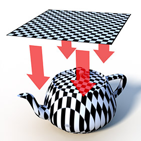
| Planar-- A 'Planar' projection is similar in concept to a movie projector, but the associated image is projected onto the surface orthographically, meaning the projection rays travel perpendicular from the virtual projection plane onto the surface. This projection type is great for flat or nearly flat surfaces. Other instances will likely cause undesirable stretching of the texture. Users can specify the axis direction, either X, Y or Z, they wish the projection to face. |
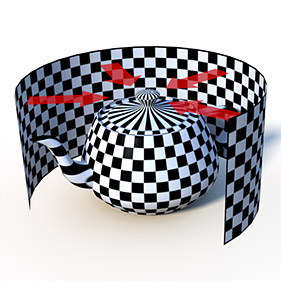
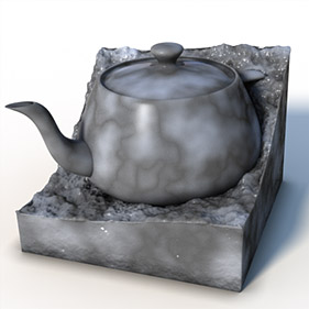
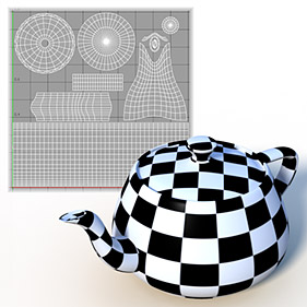
| Cylindrical-- For the 'Cylindrical' projection, the texture image is warped into a cylindrical shape and projected onto the surface. Very useful in texturing cylindrical shapes, such as labeling on various cans and bottles. Surfaces perpendicular to the projection will produce undesirable stretching of the texture as exhibited by the lid of the teapot. Users can specify the axis direction for the cylinder along the X, Y or Z axes. |
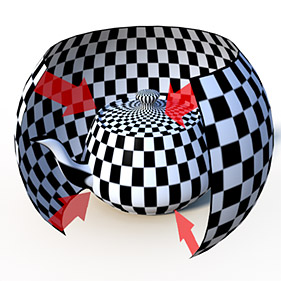
| Spherical-- For the 'Spherical' projection, the texture image is warped into a spherical shape and projected onto a surface. Useful in texturing planets and round objects such as sports balls. Spherical projections are also useful in mapping 360° panoramic images for use as environment maps. Surfaces perpendicular to the projection will produce undesirable stretching of the texture as exhibited by the spout of the teapot. Users can specify the axis direction for the sphere along the X, Y or Z axes. |
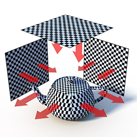
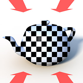
| Cubic-- For the 'Cubic' projection, the texture is planar projected through a surface from all three axial directions, X, Y & Z. A polygon receives a certain projection based on its normal direction. This projection type is best on cube shaped objects, and occasionally on detailed surfaces where texture seams are not of great concern. The main drawback is for textures that have a proper orientation are flipped on reverse faces, this is resolved by using the 'Box' projection method. |
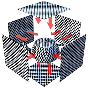
| Box-- Similar to 'Cubic' projection, but the 'Box' projection type projects a texture in a planar fashion from all six directions (like an inward facing cube), eliminating reverse projections on rear facing polygons inherent to the Cubic method. This projection type is best on cube shaped objects, and occasionally on detailed surfaces where texture seams are not of great concern. |
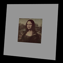
| Front Projection-- A special projection type, useful in composing 3D elements into a photograph. A 'Front Projected' image (also called a plate) is projected out from a camera or lights position (as specified by the 'Projection Camera' setting below) often onto low resolution proxy geometry or as a background environment. If the cameras position and view settings are set appropriately, rendered elements can be made to match with elements of the projected background. |
| UV Map-- UV mapping is a technique where the user can precisely plot how a 2D flat image is applied onto a 3D surface by defining a 'U' horizontal and 'V' vertical position for each polygon vertex. Many primitive object are created with automatic UV maps. Otherwise, UV maps can be easily created using any of the various UV tools available in the 'Texture > UV Tools' menu. For surfaces with a UV map defined, this is the default projection method. |
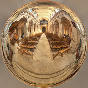
| Light Probe-- Light probe images are images used to light scenes by way of image based lighting (IBL). They are typically high dynamic range imagery (HDRI) that when applied to a scene as an Environment (and Global Illumination is enabled), brightness information embedded in the image is used to light the scene producing very realistic and natural results. A popular method of of generating these HDRI images is based on taking multiple photographs of a reflective sphere. The 'Light Probe' projection will properly unwrap this chrome-sphere style of HDRI image, projecting it out as a proper spherical background. |
|---|---|
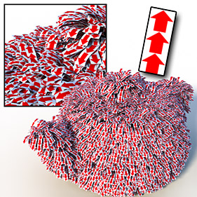
| Implicit UV-- 'Implicit UVs' are procedurally generated implied UVs used to apply image maps onto Fur fibers individually. Every fiber, when set as 'Strips' will fill the 0-1 UV space allowing appropriate images to be mapped onto the fibers, providing a means to make incredibly realistic grass and feathers, among other things. |
Projection Camera: When selecting the 'Front Projection' type one may use this setting to specify the camera to project from. Lights can be projected from as well.
Projection Axis: Defines an axial direction for any of the primitive projection types -Planar, Cylindrical, Spherical, Cubic, Box and LightProbe.
UV Map: When selecting the 'UV Map' projection type, one may use this setting to specify the defined UV map that will determine how the texture applies to the target surface. For mode information on UV mapping, please reference that page of the documentation.
Use Clip UDIM: When working with tiled UVs, the UDIM workflow allows users to automatically assign textures to specific tiles using a specialized naming scheme. When this option is enabled, the associated texture will assign to the target UV tile based on the UDIM identifier in the file name. For more information on the UDIM workflow, please reference that page of the documentation.
U/V Tile Offset: By default, MODO uses only the 0-1 UV texture space, where 0,0 is the origin. Users can define an alternate UV area to use by offsetting the origin the amount determined by the 'Tile Offset' value. (This is essentially used to manually assign UV tiles when not using the UDIM naming scheme).
Horizontal/Vertical Wrap: Controls wrapping amounts for UV image maps, effectively scaling the UV across the specified texture. A 'Wrap' value of 2.0 would repeat an image twice over the same UV space, while a wrap of 0.5 would stretch the image by half.
Horizontal/Vertical Repeat: Sets how bitmap images repeat beyond the defined image size/UV space boundary; several methods can be chosen: 'Reset' disables image tiling, 'Repeat' will tile repeatedly, 'Mirror' will tile the image flipping each subsequent image producing a backward and forwards type tiling, and finally 'Edge' will simply repeat the edge row of pixels. Users should note that these options are not visible in the GL Viewports.
 Reset | 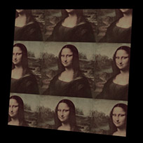 Repeat | 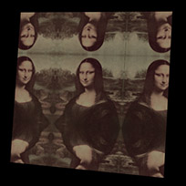 Mirror | 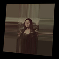 Edge |
UV Rotation: The 'UV Rotation' option allows users to rotate the image plane relative to the UV space, eliminating the need to rotate the UV mapping values manually. Rotation revolves around the 0,0 UV origin.
Random Texture Offsets: The 'Random Texture Offsets' can be used to control the relative positions of bitmapped textures on a surface based on the designated criteria. Working best with tiling textures, where there would be no distinct seam across edges, this option helps to hide or eliminate repetition by moving the textue a random direction across the surface. The amount of offset is determined by the 'Texture Offset Amplitude' option. The different offset criteria can be based on--
(none)- Disables the 'Random Texture Offset' feature when selected.
Particle and Replicas- Offsets are generated per particle and/or per Replicator item.
Mesh Parts- Offsets are generated based on individual mesh parts- multiple, individual geometric objects within a single Item layer.
Surfaces- Offsets are based off discreet sections of a single named surface across continuous geometry.
Texture Offset Amplitude: The 'Texture Offset Amplitude' determines the global strength of both the 'Random Texture Offsets' option, when one is defined and for the layer Effect 'Texture Offset'. A value of '0.0' produces no offset, a value of '10.0' is offset up to 100% of the original location. When using both the 'Random Texture Offsets' and a Texture Offset' effect. the 'Texture Offset' effect can be controlled independently by changing the texture layers opacity.
Tangent Vector Type: The 'Tangent Vector Type' option determines the tangent vector basis for an associated image map set as the surface 'normal, affecting both the baking and the display of normal maps. Normal maps are generally baked from high resolution geometry onto low resolution geometry to give the impression of higher resolution.
There are two options available- 'dPdu dPdv' defines a tangent space normal, the 'dPdu Cross Product' option defines a bi-tangent space normal that is compatible with many game engines. When baking image based normal maps, users will need to define the proper vector basis prior to actually baking the image out for the proper results.
Falloff--
Falloff Type: Falloff, when defined, will fade the texture layers opacity over the specified distance. There is cubic (3D), spherical (3D) and planar X, Y or Z.
Falloff: A setting of '0' disables falloff, when set to any value above '0', the falloff amount will act like a multiplier of the size. So a setting of 0.5 on a 1 meter texture scale will fade the texture to fully transparent over 2 meters from the locators position, a setting of 0.1 would scale it to fully transparent at 10 meters.
Texture Replicator--
The 'Texture
Replicator' function works on basically the same principle as the geometry Replicator in MODO, but provides users a means to procedurally clone an image map texture onto a surface while adding some randomization to the resulting clones. Consider the example below, on the left a seamless 'repeating' texture has been applied to the surface, but with the uniformity of the placement across the surface, the fact that it is a small repeating texture is painfully obvious. Utilizing the exact same texture in the image on the right, a particle source has been defined and some falloff and Random Size and Rotation have been applied. While there is still an amount of regularity to the surface, the texture no longer exhibits the obvious tiling of the original.
 Texture tiled across the surface looks repetitive. |  Replicator randomizes tiles eliminating repetition. |
To apply a texture Replicator to a surface, users must first assign an image map to the target surface, and in the texture layers 'Texture Locator' attributes, define a 'Particle Source', typically the target surfaces mesh item layer. Once specified, the texture is cloned to each vertex position across the surface. Users can then make adjustments to the Size, Falloff and Rotation options and then add some Random Scaling and Rotation as well.
Particle Source: Users can specify a mesh item layer as a point source for the cloned textures, when doing so, the Texture Replicator option is effectively enabled and its settings supersede all others of the Texture Locator. Once a mesh layer is defined, a single copy of the texture will be positioned and aligned to the vertices normal at each vertex point. Typically users would specify the mesh layer of the actual target surface with this option, however interesting affects can also be obtained when specifying alternate mesh layers. Keep in mind that the clones are aligned to the surface normal of the source mesh, so surface would need to be in somewhat close proximity and need to have similarly facing normals.
Particle Size: This option determines the size of the individual cloned images on the target surface. Larger numbers increase the clone sizes while smaller numbers decrease the resulting size.
Falloff Bias: Users can adjust this option to fade the texture out from its center toward the edge. Lower values keep the transparent edge toward the outer corner where higher values up to 100% push the transition toward the center.
Falloff Gain: This option determines the hardness of the falloff transition. Low values produce a very soft fade over the Falloff while higher values increase the edge hardness up to 100% producing a crisp hard edge.
Random Size: Users can use this option to define a range of random scaling applied to the individual clones.
Rotation: Each clone is initially aligned to the vertex normal position (including its rotation) of the source, but users can use this option as an offset from the initial rotation of the clones.
Random Rotation: Users can use this option to define a range of random rotation applied to the individual clones.
Local Projection: The 'Local Projection' option, when enabled, warps the replicated images to the contours of the Particle Source geometry producing a unique effect that can be more appropriate in some texturing situations.
Local Normal Attenuation: The 'Local Normal Attenuation' option, when enabled will fade the opacity of the applied texture based on its slope. The upward facing surfaces will receive the full amount of texturing, attenuating toward completely transparent at 90° angles (kind of like the accumulation of snow would look). This effect is dynamic, so as objects deform and move, the surfacing will remain only on the upward facing areas.

TIP: Texture Replicators aren't limited to using a single image map. Once defined, users can specify a Group containing any number of images as the 'Image' source in the 'Texture Layer' (under the 'Image Map' options header) and the Texture Replicator will randomly grab a member of the group for each vertex location providing additional means to randomize the look of the surface.

