
Each new scene, by default, has a single 'Base Shader' item. This Shader read the information from the entire Shader Tree and computes the effects of the illumination on all the surfaces in the scene, making the Shader the most important layer in the tree. Shaders also control the 'Rate' that pixels are evaluated before being sent to the Render item (this dices up a single pixel for things like texture computing and anti-aliasing). Additionally, they control visibility of surfaces in a scene and what rays are allowed to be seen by specific surfaces (for instance when you want only the shadow of an object to be visible). In most cases, user won't ever touch the settings in the Shader, however, in instances where specific surfaces need additional control, such as limiting Monte Carlo shading to a single surface, or hiding a group of lights from illuminating a single surface, or even hiding an entire object from the Camera, an additional Shader will need to be added with appropriate settings applied.
Assigning Item Specific Shaders
In situations where additional Shading control is required for a specific surface or item (such as making a single item invisible to a reflection), an additional Shader needs to be added to the scene. Due to the layered approach of the Shader Tree, any additional Shaders will need to be placed above the 'Base Shader' within its own Material Group mask (otherwise the settings of the Base Shader will simply override it). A simplified approach would be to apply an item specific Shader, these types of Shaders work outside of the Shader Tree itself, acting as individual Item based overrides to the settings of the Shader Tree. Item Shaders are added and selected within the Items list. RMB+clicking on the target layer, users can select the "Create Item Shader" option from the contextual menu, assigning the Shader to the Item. Clicking on the small '+' sign preceding the layer name will display the shader below the item allowing it to be selected and its attributes modified in the 'Properties' panel. The following video explains the process-
When applying the Item Shader for a specific task, users can manually disable the 'Control' (or 'Compute') options except for the targeted adjustment. If one wanted to control the visibility of the Item, this could be accomplished by disabling 'Compute Shading', 'Control Quality', 'Control Lighting' and 'Control Fog' options and then toggling the 'Visible to Camera' option disabled. Now the target item will be invisible to the Camera, but still cast a shadow and show up in reflections. Shaders applied to Items really simplify certain tasks like these and keep the Shader Tree free of these additional layers.
For more information regarding adding and working with Shader Tree Items Layers, please reference the Shader Tree page of the documentation.
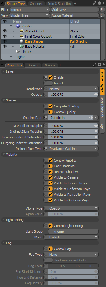 Layer--
Enable: Toggles the effect of the layer on and off, duplicating the functionality of toggling visibility in the Shader Tree. When disabled (un-checked), the layer has no effect on the shading of the scene. However, disabled layers are saved with the scene and are persistent across MODO sessions. When there is only a single Base Shader in a given scene, disabling the Shader has no effect, otherwise, the scene simply wouldn't render.
Invert: Inverts the illumination of the scene/layer producing a negative effect.
Blend Mode: Affects blending between different layers of the same effect type, allowing user the ability to stack several layers for different effects. For more on blending, please reference the 'Blend Modes' page of the documentation.
Opacity: Changes the transparency of the current layer. Reducing this values will increasingly reveal lower layers in the shader tree if present, or dim the effect of the layer itself on the surface.
Shader--
Compute Shading: When 'Compute Shading' option is enabled, the Shader will compute the Shading attributes for the scene (such as Diffuse, Specular and so on). When applied as an Item Shader (where the Shader itself is applied in the Items list rather than the Shader Tree) the Shader is computed outside of the Shader Tree acting as an override. Disabling this option in that case will revert to the Shader Tree evaluations.
Control Quality: When 'Control Quality' is enabled, the Shader can be used to control the Shading Rate, multipliers, saturation and Indirect Illumination type settings. When applied as an Item Shader (where the Shader itself is applied in the Items list rather than the Shader Tree) the Shader is computed outside of the Shader Tree acting as an override. Disabling this option in that case will revert to the quality setting evaluations of the Shader Tree.
Shading Rate:The Shading Rate (also known as the "Coarse Shading Rate") determines how finely to shade each pixel in the materials feeding the selected Shader Item during initial shading. The default value of 1 indicates that the pixel will be evaluated once before being evaluated for further refinement (see Refinement Threshold). Decreasing the Shading Rate results in a more finely evaluated pixel which generally yields longer render times. For instance, if you change the value to .5 the pixel is effectively cut in half horizontally and vertically and each "sub pixel" is evaluated. In this case you have reduced the rate by half but increased the amount of evaluation by 4 times. Keep this in mind as small changes to the shading rate can yield large changes to performance.
Generally the Shading Rate can be left at one and further refinement can be achieved via the Antialiasing level or the Refinement Shading settings. However, in the cases of aliasing seen in reflections or refractions or on procedural textures it is possible to rectify them via the Shading Rate setting. Since this will effect all pixels evaluated it is a fairly 'brute force' solution. Therefore, you should manually restrict the pixels that are effected by the Shading rate by creating Shaders for specific problem areas via Masks and only decrease the Shading Rates where absolutely necessary.
Direct Illumination Multiplier: Direct Illumination is light coming from traditional 3D light sources such as Directional, Spot, Area, Distant, Cylinder, Dome, and Point. At the Shader item level it is possible to globally affect the direct light intensity via the Direct Illumination Multiplier. By default the value is set to 100%. If we imagine a project with three lights of varying intensity such as 100%, 70% and 30%, setting the 'Direct Illumination Multiplier' to 50% would drive these values down to 50%. 35% and 15% respectively. This is often a handy method for tweaking overall light effects as well as balancing Direct and Indirect light contributions.
Indirect Illumination Multiplier: Indirect Light comes from global illumination sources such as luminous geometry, image based lighting via environments and simple bounced light from diffuse surfaces. The Indirect Illumination Multiplier provides a global method for controlling the Indirect light contribution to the final render. This is very useful when Indirect Light sources are too subtle/pronounced or for simply balancing Direct and Indirect Light contributions.
Incoming/Outgoing Indirect Saturation: One of the many benefits of indirect illumination is the color bleeding between surfaces. As rays take into account not only the color of the lights, and the environment, but the surfaces color as well. The 'Incoming/Outgoing Indirect Saturation' setting allows the user to control the strength of the colors or saturation amount generated by indirect illumination independent of the illumination itself, with separate settings for both incoming rays and outgoing. Increasing the value above 100% will make the colors stronger and more saturated, and values below 100% will decrease the effect.
Indirect illumination Type: Generally, indirect illumination is controlled globally through the Render Properties Global Illumination tab. In some instances, the user may want to control the type of global illumination per surface by using a shader with an associated mask. This gives the user the option of using Irradiance Caching for say an exterior scene, but on complex surfaces such as the trees and bushes, the monte carlo method would provide better results. The user could create a selection set for just the trees and bushes (Select > Assign Selection Set), and in the shader tree, add an additional material 'Group' item above the base shader. In the group properties panel set Tag Type to 'Selection Set' and highlight the named set under 'Polygon Tag'. In this group add its own 'Shader' and set the properties 'Indirect Illumination Type' to 'Monte Carlo'. Now most of the scene will use irradiance caching while only the trees and bushes would use Monte Carlo. The Indirect Illumination type will draw its values from the Render Properties Global illumination tab. The number of rays used for the Monte Carlo method is indicated by the 'Indirect Rays' value of the aforementioned properties tab of the Render item.
Visibility--
There are several toggle options to control visibility of various attributes of the elements feeding the shader. For instance, with these controls you could create a bright luminous polygon that is visible to Indirect Illumination but invisible to reflections, ray traced shadows, reflection and the camera. This would create a nice virtual light element that can be placed anywhere in the scene for illumination purposes without worrying about it effecting any other visual aspect of the project. The options include:
Control Visibility: When the 'Control Visibility' option is enabled, the Shader will compute the visibility attributes for the item or scene. When applied as an Item Shader (where the Shader itself is applied in the Items list rather than the Shader Tree) the Shader is computed outside of the Shader Tree acting as an override. Disabling the 'Control Visibility' option in that case will revert to the Shader Tree evaluations for visibility.
Cast Shadows: Disabling this toggle will cause all elements controlled by the shader to be ignored by shadow rays so they do not create any shadows in the scene. Light will simply pass through the elements. This will not disable shadow effects from indirect illumination as this only affects direct light sources.
Receive Shadows: Disabling this toggle causes the elements to stop receiving ray traced shadows from other geometry in the project.
Visible to Camera: Disabling this toggle will simply hide any item or element controlled by the shader from the camera. These elements may still appear in shadows, reflections and refractions even when hidden to camera.
Visible to Indirect Rays: Indirect Light is any light calculated during Global Illumination such as luminous geometry, Images used as light sources and other light bounced from geometry. Toggling this option off will remove the elements controlled by the shader from Indirect Light calculations.
Visible to Reflection Rays: Disabling this value will remove the elements controlled by the shader from reflecting in mirror surfaces.
Visible to Refraction Rays: Disabling this value will cause the elements controlled by the shader to be invisible when looking at them through refractive surfaces.
Visible to Occlusion Rays: Disabling this value will cause the elements controlled by the shader to be invisible to Occlusion Ray calculations.
Alpha Type: The 'Alpha Type' selector allows the user to choose how surfaces contribute to a rendered alpha channel. When set to 'Opacity' the transparency of each individual surface determines the alpha value. 'Constant' allows the user to specify a fixed alpha value for all associated surfaces. 'Shadow Catcher' is a slightly different function, as it makes all associated surface attributes invisible, exclusively rendering shadows cast by direct and indirect illumination. This is a great tool for composing rendered images with background photos right in MODO. A ground plane can 'catch' the shadows cast by other object, without contributing any shadows of its own. When a photo is specified as a background, the objects and shadows all render together in one pass. This video explains the process-
Alpha Value: When 'Constant' is selected as the alpha type, the 'Alpha Value' overrides surface opacity settings and determines to what degree surfaces contribute to a rendered alpha channel.
Control Light Linking: When the 'Control Light Linking' option is enabled, the Shader will compute the visibility of light groups for a given item or surface. When applied as an Item Shader (where the Shader itself is applied in the Items list rather than the Shader Tree) the Shader is computed outside of the Shader Tree acting as an override. Disabling the 'Control Light Linking' option in that case will revert to the Shader Tree evaluations for light linking.
Light Group: Light linking allows users to control, on a shader level, what lights in a scene effect what surfaces. The 'Light Group' selector allows the user to specify which group of lights to control. Light groups can be easily made in the 'Groups' palette. Click 'new group' to create a base group, rename it if you wish, and add items by selecting the lights in the 3D viewport, hold down shift to select multiple items. Now right click on the group title and select 'Add Items' from the drop down menu. Users can also drag and drop items directly from the 3D viewport onto any group item to add them.
Mode: The 'Mode' selector allows the user to specify how the lights affect surfaces, If set to 'Include', the lights will affect the shaded surfaces and set to 'Exclude, the lights will not.
Fog--
The Fog option produces a simulated (non-volumetric) fog effect by applying a user defined color to relevant materials with increased intensity as the geometry is further from the camera. This is also a great option to fade objects into a background, increasing the apparent depth (and likewise scale) of a scene. Fog can also be specified in the Environment Material item with similar options. The Environment Fog option differs in that it always uses the the environment color, where with the Shader Fog, any color can be specified. (click to enlarge samples)
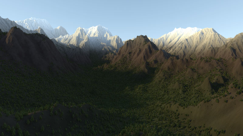 No Fog | 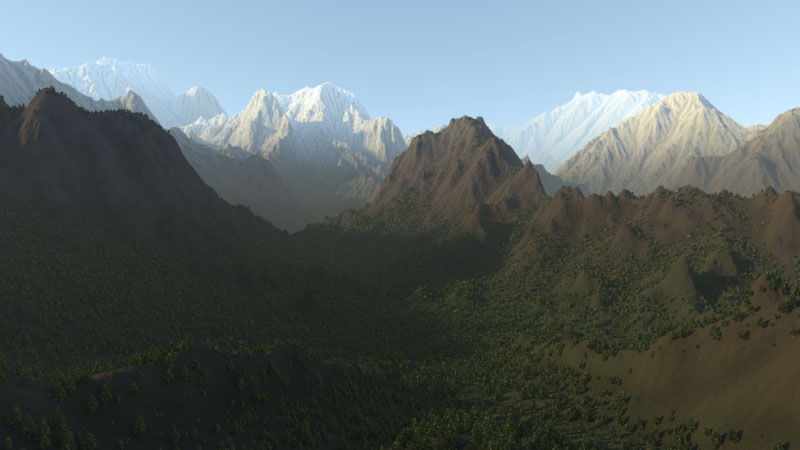 Linear Fog | 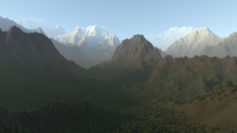 Exponential Fog | 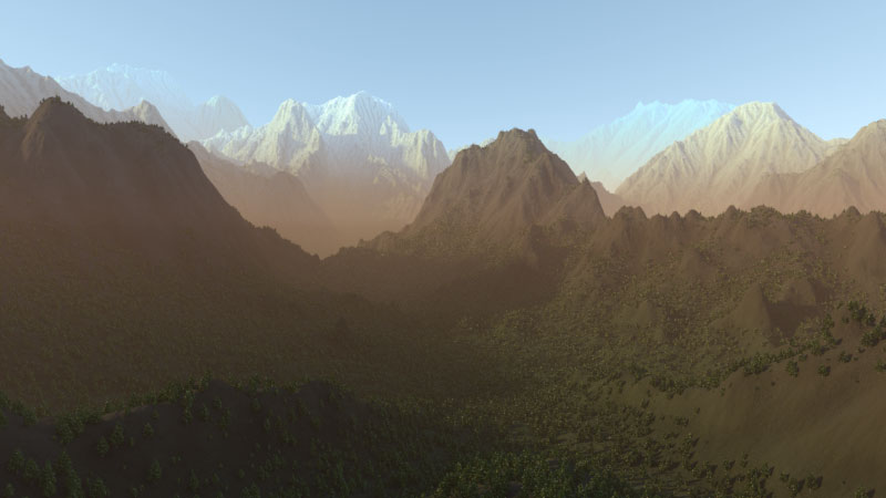 Underwater Fog | 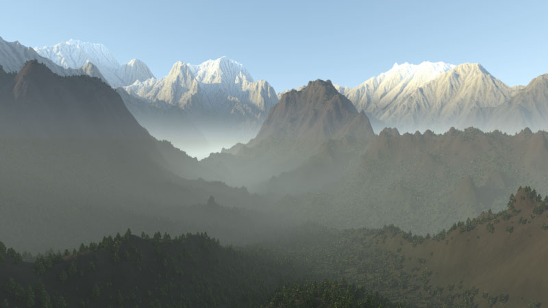 Layered Fog |
Fog Type: The Fog Type popup allows you to choose from the different fog types-
None- Disables Fog from rendering.
Linear- When selected, Fog will render in the scene based on the Start and End distances, where there is no fog up to the starting distance, then surfaces will attenuate toward a solid color and maximum Fog density at the end distance.
Exponential- When selected, Fog will render starting at the cameras position, increasing in strength the further a surface is from the camera. Based on exponential values, the strength will increase non-linearly and is directly influenced by the 'Fog Density' setting (so for very large scenes, you will want to use a very small value).
Underwater-
The 'Underwater' fog option is basically the same as the Exponential function, except that the fog will have a tendency to absorb the environment color more readily, producing an environment colored cast. It also reduces color saturation with distance. The example above is a late afternoon environment, so the reds of the setting sun influence the fog color. For a true underwater look, define a blue or teal color, or set the environment to a 2 or 4 color gradient blues or greens and enable the 'Use Environment Color' option.
Layered- The 'Layered' fog option produces a ground fog like effect where the fog density increases with both depth and height.
Use Environment Color: This option is only available when Backdrop Fog has been enabled. With backdrop fog MODO adds the fog color to all materials with increasing intensity as the distance to the camera increases. With Use Environment Color active the Environment Material or textures will be used to color the fog. This option will give the illusion that the mesh is fading into the background.
Fog Color: This color component determines the color value that is applied to materials receiving fog.
Fog Start/End Distance: When the Fog type is set to linear, users can specify specific starting and ending distances for the fog effect.
Fog Density: This percentage value determines how thick the fog is just in front of the camera. The default value of 10% indicates that geometry just in front of the camera will have a 10% blend of the fog color. The density of the fog will increase as it recedes further from the camera.

