


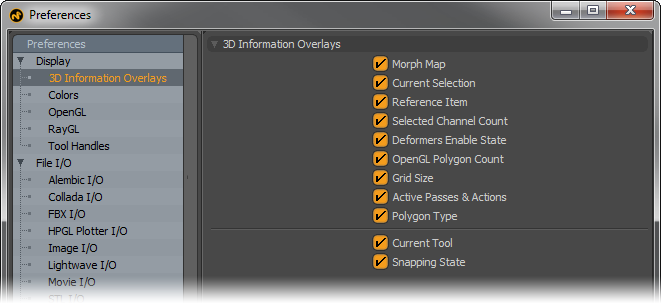
3D Information Overlays (aka 3D viewport HUD)
Each 3D viewport displays a variety of information as a HUD (heads-up display) directly in the viewport. Users can control what information is viewed by these toggles-
Morph Map- Displays the name of the currently selected morph map, if available.
Current Selection- Displays selected element information, based on the current mode (component, item or otherwise).
Reference Item- Displays the name of the source file for selected items that are part of a Referenced scene.
Selected Channel Count- Displays the number of currently selected (active ) channels in the 'Channels' viewport useful for keyframing.
Deformers Enable State- Displays current state of 'Deformers'. Animated Deformers can be enabled in the 'Viewport Options'.
OpenGL Polygon Count- Displays the number of GL polygons, including those added by Subdivision Surfaces.
Grid Size- Displays the real-world measurement equivalent of the current grid divisions.
Active Passes and Actions- Displays any active 'Passes' and/or 'Actions' by name that are selected
Polygon Type- Indicator displays polygon type for active mesh layers-- 'Face', 'Subdiv', 'Catmull-Clark' or 'mixed'.
Current Tool- Displays current tool information as well as info for 'Falloffs', 'Action Centers' and 'Snap'.
Snapping State- Displays the current enabled options for Snapping.
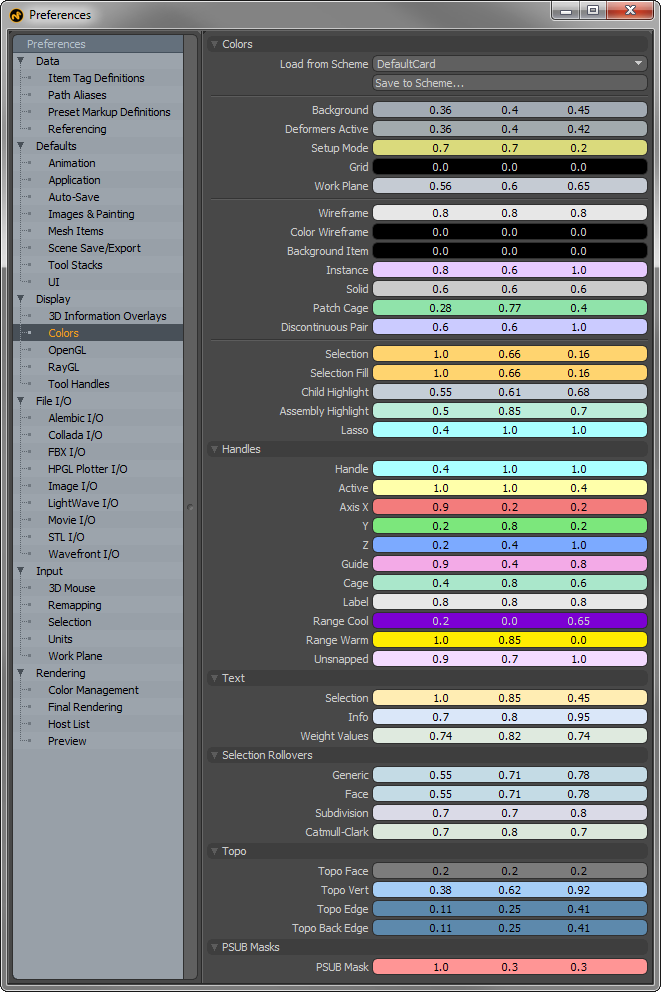
Colors--
Users can customize the colors of many aspects of MODO related to the 3D viewports (application specific viewports don't have directly editable color schemes). Users should note that modifying colors in 'Preferences' will not modify the actual default viewport colors. In order to apply a color scheme to a viewport, users will first need to adjust the colors in this section, then use the 'Save to Scheme' function and assign a new name using this dialog box-
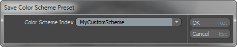
Once a scheme name has been set, users will need to switch back to the particular 3D viewport they wish to apply the scheme to. Presets can be applied on a per-viewport basis, determined by its 'Active' status. Active viewports are separated by the thumb changing to an orange color (the thumb is the small dimple in the upper left corner of a 3D viewport). Users can set any viewport as 'Active, by simply LMB+clicking anywhere over the viewport window. Next, invoke the menu bar command "View > Viewport Color Scheme" and select the previously saved scheme from the drop-down menu list. The following elements of MODO can be customized--
Background- The viewport background color when GL Background option is set to 'None' or 'Gradient'.
Deformers Active- The viewport background color when the 'Enable Deformers' option is enabled.
Grid- The main ground plane grid visible in every 3D perspective viewport.
Work Plane- The adjustable construction plane.
Wireframe- Default 'Uniform' wireframe draw color, can be over ridden by individual item Draw options.
Color Wireframe- Default 'Color' wireframe draw color, can be overridden by individual item Draw options.
Background Item- Inactive mesh color, also considered Background or Unselected.
Instance- Instanced item duplicates.
Solid- Geometry display color when using the 'Solid' GL viewport display style.
Patch Cage- When SubDivision display cage option is enabled, this determines its color.
Discontinuous Pair- Color referencing discontinuous edges in UV mode.
Selection- Element selection color for all selection types, Component, Item and otherwise.
Selection Fill- Fill Color of Selected Elements, can be set different from selection itself.
Child Highlight- When a Parent item is selected, child items can have a custom color referencing their relationship to the selected item.
Assembly Highlight- Highlighted mouse-over color of Assemblies.
Lasso- Color of line drawn when drag selecting elements with a lasso.
Handles--
Handle- Unselected action area of tool.
Active- Selected Action area of tool.
Axis X/Y/Z- Colors for constrainable tool handles for each axis.
Guide- When using Snapping > Constrain to > Guides, this option determines guide color.
Cage- Color for Spline/Curve Cage edges.
Label- Item Label as determined by 'Display' options.
Range Cool- When "View > Show Falloffs" is enabled, determines cool range of falloff.
Range Warm- When "View > Show Falloffs" is enabled, determines warm range of falloff.
Unsnapped- When snapping elements, a small pre-highlight displays when elements are in close proximity, defined by this color.
Text--
Selection- Color for on-screen informational text display of selected elements.
Info- Color for on-screen informational text display.
Weight Values-
Selection Rollovers--
Generic- Generic selection roll-over pre-highlighting color.
Face- Geometry face roll-over pre-highlighting color.
Subdivision- MODO Subdivision surface geometry roll-over pre-highlighting color.
Catmull-Clark- Catmull-Clark geometry roll-over pre-highlighting color.
Topo
Topo Faces- Polygon faces while using the 'topo' display mode option.
Topo Vert- Vertices while using the 'topo' display mode option
Topo Edge- Edges while using the 'topo' display mode option
Topo Back Edge- Rear facing polygon edges while using the 'topo' display mode option
PSUB Masks
PSUB Mask- Color of sculpting mask overlay
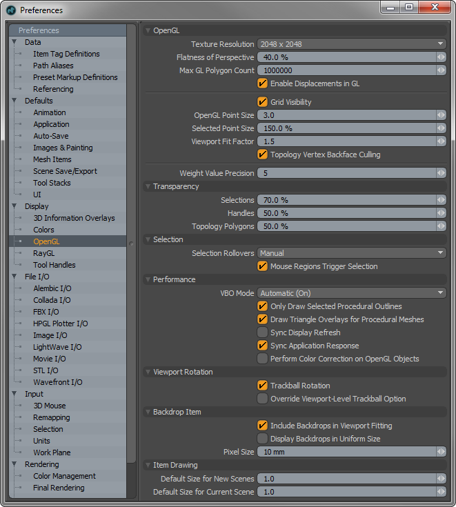
OpenGL--
Texture Resolution: This values (set as powers of '2') determines the largest bitmap texture size displayable in MODO 3D viewports before MODO will resort to mip-mapping, which is a method of subsequent resamples of an image at a lower resolution that enable faster image drawing to the 3D viewport. Higher settings will increase image quality, but require greater video ram.
Flatness of Perspective: This option determines the amount of perspective in the 3D perspective viewport. Similar to the 'Field of View' option in the Camera options panel. The higher the value, the flatter the perspective, the lower the value the more distorted and extreme the perspective becomes.
Max GL Polygon Count: This option defines an upper limit to the number of polygons visible in a 3D viewport. It triggers an error message allowing users to cancel the previous operation if it were to exceed the defined amount. This option was created mostly to help users from locking up a system when trying to subdivide a model too many times when using Multiresolution sculpting.
Enable Displacement in GL: This option determines if displacement effects are displayed in the GL viewports as actual polygon displacement. When disabled, displacement will simply display in the 3D viewports as a bump map.
Grid Visibility: This option determines the default visibility state of the ground plane grid visible in 3D viewports. It is enabled (visible) by default.
OpenGL Point Size: This option determines the size of the on-screen display of vertices, specified in screen pixels. The default value is 3. Consequently, it also controls the selection hit area for selecting vertices.
Selected Point Size: To make it easier to see their on-screen display, selected (highlighted) vertices can be displayed larger in the 3D viewport, an amount determined by this option. Scale is based off the original 'OpenGL Point Size" option.
Viewport Fit Factor: Users can automatically frame the view of all the elements of a scene to the bounds of the active viewport by using the menu bar commands "View > Fit All" or "View > Fit Selected" (or keyboard equivalents 'A' or 'Shift+A' respectively). This option determines the scaling of the fit. '1' is essentially 100%, fitting the bounding box of the elements to that of the viewports shortest length. The default of '1.5' gives a little breathing room around the elements and ensures the view fits into view regardless of bounding box size.
Topology Vertex Backface Culling: When enabled, this option disables the display of vertices for rear facing polygons while using the topology display mode. This can make it easier to distinguish foreground vertices when editing.
Weight Value Precision: If a Weight Map and Vertices are selected with the 'Show Weight Values' option enabled, then the 'Weight Value Precision' option determines the number of decimal places shown for the weight values in the GL viewport.
Transparency--
Selection: When viewing a selection through an opaque surface, this option determines the opacity of the selection highlighting through the surface (kind of like an X-ray). Especially helpful in differentiating front and rear facing selections.
Handles: When viewing tool handles through an opaque surface, this option determines the opacity of the handle itself, making it possible to see the handles through the surface (kind of like an X-ray).
Topology Polygons: This option determines the transparency of forward facing polygons while in the topology display mode.
Selection--
Selection Rollovers: Pre-highlighting of elements in a scene helps users to make better selection, making it clear as to what elements will be selected when the mouse button is clicked. The 'Selection Rollover' option determines how the highlighting occurs-
None- No pre-highlighting of elements in the scene.
Manual- Pre-highlighting of elements is based on the current mode (vertices, edges, polygons, items, etc.).
Closest- Pre-highlighting the nearest geometric component element regardless of mode.
Mouse Regions Trigger Selections: With this option enabled, users can automatically switch between component modes (vertex, edge, polygon) by simply RMB+clicking over the target element. Can be combined with 'Closest' selection rollover to aid in determining the proper element to click on.
Performance--
VBO Mode: VBO stands for 'Vertex Buffer Object', a method of working and displaying geometry in OpenGL. VBO's offer substantial performance gains over the older immediate mode rendering method, but may also cause problems with older video cards (or video cards with lacking drivers). MODO will try to determine the best mode when set to 'Auto', depending on the video cards driver. Users can also manually enable/disable the option with the On/Off options to increase stability.
Only Draw Selected Procedural Outlines: When this option is enabled, MODO will only draw the surface outline for procedural geometry (such as the 'Gear' item). When disabled, MODO will draw any individual triangles that make up the surface.
Sync Display Refresh: Also know n as 'Vsync', when enabled this option will help with tearing in the GL viewports but may cause lag with larger meshes and lower framerates.
Sync Application Response: When enabled, this option will sync the application with the 3D OpenGL viewports reducing lag, but it can sometime also significantly reduce the 3D viewports framerate (entirely dependent on the Scenes contents).
Performs Color Correction on OpenGL Objects: This option toggles the Color Management of the 3D viewports. When enabled the 3D viewports will be adjusted using the current 'Color Management' settings. When disabled the viewports will not be corrected. Note that in complex scenes corrected viewports may reduce display performance.
Viewport Rotation--
Trackball Rotation: This options determines the default navigation rotational type. Trackball style navigation is a common way to rotate the view of a scene, as if the viewport itself was a giant trackball, allowing multiple axes rotation based on the mouse's viewport position. Disabling this option limits viewport rotations to only two axes. This setting can be over-ridden on a per viewport basis.
Override Viewport-Level Trackball Option: When enabled, this option disabled an individual viewports ability to over-ride the Viewport Rotation preference setting, in essence locking all viewport rotation options to the same preference setting.
Include Backdrops in Viewport Fitting: When using the 'Fit' function of a viewport, enabling the 'Include Backdrops' option will account for the size of any visible Backdrop items when calculating bounding box size for the fit action.
Display Backdrops in Uniform Size: When this option is enabled, Backdrop items will ignore the image size, instead basing the scale of the backdrop off of the items 'Scale' value.
Pixel Size: When importing bitmap images for use as Backdrops, the 'Pixel Size' option determines the measurement of a single pixel in an image upon import, allowing users to place backdrop images scaled to real world size. For example, if 'Pixel Size' is set at 10mm, then a 512x512 image will import at 5.12 meters in size.
Item Drawing--
Default Size for New Scenes: Determines the default drawing size in the 3D viewports for non-mesh items, such as Cameras and Lights. Users can also adjust the scaling values manually in the 'Display' viewport.
Default Size for Current Scene: Determines the default drawing size in the 3D viewports for non-mesh items added after a scene is created; such as Cameras and Lights when added to a new scene. Users can also adjust the scaling values manually in the 'Display' viewport.
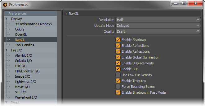
Resolution: When RayGL in-viewport render preview is utilized, this option determines the resolution of the rendered image, initially based off the on-screen size of the 3D viewport. Lower resolutions will update more quickly. There are three options-
Full- Renders at the same pixel resolution of the viewport.
Half- Renders at ½ the resolution of the viewport.
Quarter- Renders at ¼ the resolution of the viewport.
Updates: This setting determines the way that the RayGL preview updates (or renders) while working in a 3D viewport- There are three options-
Delayed- This option will update the viewport preview when the mouse button or tool handle is released.
Lazy- This option will update the viewport each time a pause is encountered, regardless of mouse or tool state.
Synchronous- This option will continuously update the viewport, as best as the system is able to process the data, reducing resolution as necessary to keep up.
Quality: When RayGL in-viewport render preview is utilized, this option determines the quality of the rendered display.
Draft- Renders image using a reduced number of ray samples (as specified in the Rendering Preview section under Preview Draft Quality Settings), producing a faster, though less accurate result.
Final Render- Renders image using the same number of rays as specified by the user for the final render.
Extended Refinement Passes- Renders image with additional ray samples beyond any value specified for IC, MC, Reflections, Refractions, Transparency and Subsurface Scattering up to the number of rays specified within the 'Rendering' Preferences section, under 'Preview'.
RayGL Toggles: For memory or calculation intensive scenes users may wish to disable certain effects from being considered in RayGL processing. The various options can be toggled independently -Shadows, Reflections, Refractions, Global Illumination, Displacements, Fur and Fur Low Density. The final setting users can enable reducing the polygons count of fur texture layers without disabling fur entirely.
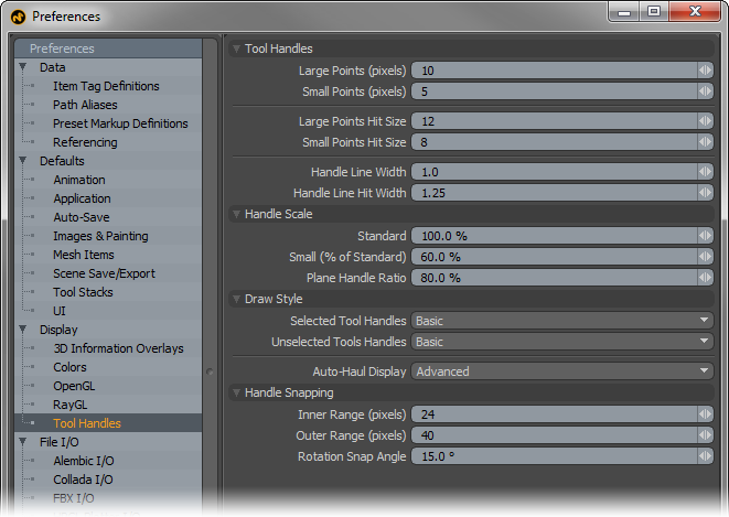
Large\Small Points: Determines the visible size, in pixels, of manipulator handles displayed on tools (such as those on the Curve drawing tools).
Large\Small Points Hit Size: Determines the hit range, or area where a mouse click will affect the particular tool handle. Typically this value will be larger than the handle size to make it easier to select a particular handle, but making it too large can make it difficult to select a specific handle in a tight cluster.
Handle Line Width: Determines the width, in pixels, of the lines drawn for tool handles, such as the widgets for Move, Rotate and Scale.
Handle Line Hit Width: Determines the hit range, or area where a mouse click will affect the particular tool handle. Typically this value will be larger than the handle size to make it easier to select a particular handle.
Handle Scale--
Standard: Users with very large or very small screens may prefer to set the default size of the tool handles larger or small using this setting. Handles will stay consistent in size regardless of viewport scaling. Users can also interactively scale tool handles by pressing the '-' and '=' keys. (easier to remember as '-' & '+' [minus and plus] though)
Small (% of Standard): Some tools have a smaller secondary handle. Users can adjust its size here based as a percentage of the "Standard' amount.
Plane Handle Ratio: Many tools have additional plane handles, that constrain actions to two axes simultaneously. Users can adjust the plane tool handles size based on the 'Standard' amount.
Draw Style--
Selected Tool Handles: Determines the default drawing behavior for tool handles-
Invisible- No handles display in the viewport.
Basic- Basic tool handles display allowing users to constrain certain function when used, based on the particular tool.
Advanced-
When present/available, additional controls or handles will appear on screen to aid in setting certain options for a tool or item. For example, when selecting the Camera item with and any tool with 'Advanced' handles, additional controls become visible for setting 'Focal Distance' and 'F-Stop'.
Unselected Tool Handles: Depending on the tool, additional handles may display in the viewport, especially those related to setting falloff positions and sizes. The 'Unselected Tool Handle' option determines the drawing options for these types of additional handles.
Auto-Haul Display: Some tools can be enhanced with additional on-screen controls. For example, advanced in-viewport sliders can specify Bevel 'Shift' and 'Inset'. This option determines whether or not to draw such additional helpers.
Off- Disables display of additional on-screen tool Auto-Haul Displays.
Basic- Displays only basic tool handles.
Advanced- Displays only advanced tool handles when available.
On- Displays on Screen Auto-Haul handles defaulting the settings of the preset itself as determined by its options in the Tool Pipe.
Handle Snapping--
These are the default values, in pixels, for the distance from a snapping target where the cursor first gets snapped.
Inner Range: Determines the actual snapping range.
Outer Range: Determines the range to highlighting elements for snapping to.
Rotation Snap Angle: Sets the angle of the fixed intervals for any rotation tools. Activated only when pressing the 'Ctrl' before rotating the target element.