


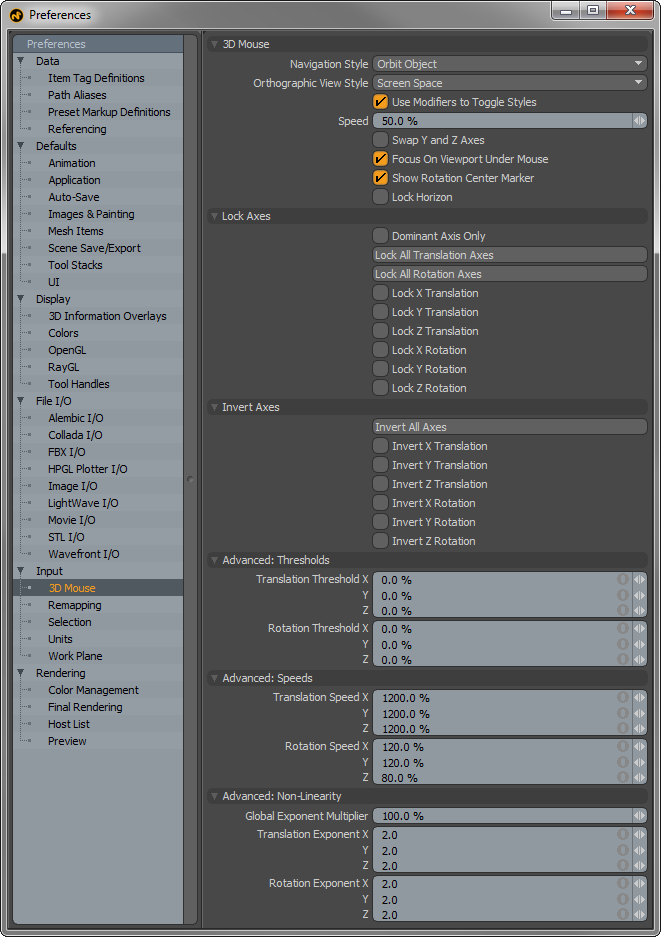
3D Mouse--
Navigation Style- The 3D Mouse provides two main navigation styles which users may select based on preference-
Camera Walkthrough- Â Moving the puck moves the viewport's camera as though you were moving the camera itself. Â Pushing the puck to the right moves the camera to the right (and thus the scene appears to move to the left). Â Can be thought of as similar to playing a first-person video game.
Object Orbit- Â Moving the puck moves the viewport's camera such that you seem to be moving the item in the view. Â Pushing the puck to the right moves the camera to the left (thus making it appear that the object is moving to the right). Â Twisting the puck rotates the camera around the object, as though the object was spinning around in front of you. Â The center of rotation is determined by the "blue dot" (aka "Auto Rotation Center"), which appears at the center of the viewport when you start manipulating the puck. Â If the item under dot fills >80% of the view, the blue dot represents a point on the surface of the model that is tracked in 3D space until you release the puck (at which point the blue dot will re-center at the center of the viewport when you touch the puck again). Â If <80% of the view is filled with the object, the object's bounding box center is used as the center of rotation.
Orthographic View Style:
World Space-Â The translation axes of the puck move in world space, irrespective of the current orthographic view. Â Thus, pushing left/right on the puck always moves on the world X axis, even if the orthographic view is showing the Left or Right (and in which case you won't appear to see any movement, since you're moving perpendicular to the view). Â Best used/demonstrated with the Model Quad view
Screen Space- The translation axes move relative to the current view: x20left/right moves on the horizontal axis, and up/down moves in the vertical axis. Pushing in/out will change the view's zoom
Screen Space (Swap Y and Z Axes)- Pushing the puck left/right will move left/right just like in Screen Space mode, but pushing the puck forward/backward (like a mouse on a desk) will move the screen up/down, while pulling up/down will zoom in and out. Basically, the Y and Z axes are swapped.
Use Modifiers to Toggle Styles: When enabled, 'Alt' toggles between the two 'Navigation Styles' as long as it is held down. Similarly, 'Shift' and 'Ctrl' will toggle between the two 'Orthographic View Styles' as long as they are held down.
Speed: This is a global speed modifier, a scaling value applied to the 3D mouse's input values to make the mouse move faster or slower. This is not capped to 100%, so you can set it to 200%, etc. if you want it to go faster.
Swap Y and Z Axes: Will switch the Y axis with the Z axis, useful for people who think of the screen as lying in a desk (usually CAD/architecture users) vs. those who think of the screen as vertical (usually video-centric users).
Focus on Viewport Under Mouse: When enabled, the 3D mouse movement will apply to whichever viewport the mouse cursor is currently over (that can accept 3D mouse input, of course). If disabled, the user must first interact with the viewport (by clicking in it with the mouse or by rolling the mouse wheel) before the 3D mouse will switch focus, this is indicated by the orange color of the 'thumb'. In both cases, if the mouse is not over a view that can accept 3D mouse input, the last view that can accept such input continues to get input.
Lock Horizon: Maintains a level horizon when navigating (this is different than just disabling the Z axis rotation).
Lock Axes--
Dominant Axis Only: Only the axis that has the most force applied to it will be used, all others will act as though they are idle. Useful if you only want to move on one axis at a time, but don't want to have to keep toggling the 'Lock' buttons.
Invert Axes--
Invert All Axes: A simple script that toggles the state of all of the Invert buttons. There are similar scripts (and buttons) to lock all the translation or rotation axes.
Advanced Thresholds--
Translation/Rotation Threshold: The 3D mouse has a range of 0-100%. Thresholds allow the user to require a certain amount of force on an axis before it will register as movement. If set to 10%, you need to push the mouse harder before you see any movement, at which point the remaining 10%-100% range will be expanded to be the new 0%-100% range. Useful for new users that keep accidentally moving on multiple axes at once, and can be thought of as training wheels. However, it also can make the puck feel unresponsive due to the extra force required to see any movement, and may keep users from becoming proficient at controlling multiple axes at once. Most users should leave these at 0%.
Advanced Speeds--
Translation/Rotation Speed: Per-axis speeds, should the user want to change the speed of an individual axis. The global speed control is applied on top of these values.
Advanced: Non Linearity--
Global Exponent Multiplier: Globally scales the non-linear exponents in the same way that the global speed scales all speeds. So, it provides an easy, high-level way to further adjust all of the exponents at once.
Translation/Rotation Exponent: Determines the non-linearity of the 3D mouse movement. The original linear implementation made it difficult to do both well-controlled small movements and larger movements. With non-linearity, more of the 0-100% input range of the 3D mouse is used for fine control, but coarse control is still available by simply pushing the puck further.
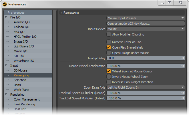
Remapping--
Mouse Input Presets: Users coming to MODO who are familiar with another 3D application might find themselves unable to switch into MODO mode. The 'Mouse Input Presets' are meant to adjust the mouse navigation controls to mimic those of the chosen application reducing users navigational stumbling, making it easier for switching back and forth between the other program. A variety of options are available representing a number of popular 3D programs.
Convert MODO 103 Key Maps: This legacy option converts MODO 103 keymaps to the current version. User would need to load v103 keymap configs using the 'Config Import' function found in the file menu prior to running this option.
Input Device: This option determines how MODO interprets input commands, users can choose either a 'Mouse' or 'Tablet' as the main form of input. Tablets typically use an absolute positioning based on a stylus' position on the tablet surface, whereas a Mouse uses a relative position based only on the initial position of the cursor. Users using a Tablet with relative positioning should set this option to 'Mouse'.
Allow Modifier Chording: When enabled, modifier keys can trigger 'Chording', when disabled, only mouse buttons can trigger chording. Chording is the use of multiple mouse buttons simultaneously. It should be noted that chording has been widely recognized as a key contributor to carpal tunnel syndrome and other repeated stress injuries. The Foundry recommends that users avoid chording to prevent unnecessary muscle strain.
Numeric Enter as Tab: When enabled, pressing the 'Enter' key on the numeric keypad will function the same way as pressing the Tab key does, by advancing the cursor to the next logical data field.
Open Pies Immediately: This option determines whether there is a slight delay to the opening of Pie Menus when disabled, or if the menus open immediately when enabled. For users not accustomed to Pie Menus, the delay may be helpful in eliminating menus from popping open unexpectedly on errant key presses.
Open Dialogues Under Mouse: This option forces new dialog boxes to always open at the current mouse position (such as the 'Save As' and 'Open' file dialogues). When disabled, dialog boxes will open in the same position as the last open dialog box.
Tooltip Delay: Defined in seconds, this option determines the length of time before the tooltip info display opens when hovering the mouse pointer over a button or function of MODO. The default value is 0.8 seconds.
Mouse Wheel Acceleration: This percentage value determines the speed at which MODO zooms in or out when using a mouse's scroll wheel. Higher values will zoom faster, while lower values will zoom more slowly.
Wheel Zoom at Mouse Cursor: When this option is enabled, zooming in any OpenGL viewport with the mouse scroll wheel will center the zoom based on the mouse's position over the viewport, when disabled, the mouse's position is disregarded and the viewport will zoom based on its center.
Invert Mouse Wheel Zoom: This option inverts the zooming behavior of the mouse wheel. Pushing forward on the wheel will push out instead of in.
Zoom Drag Axis: This option determines the directional behavior when hauling in a 3D viewport when zooming. The options are 'Left to Right', 'Right to Left', 'Bottom to Top' and 'Top to Bottom'.
Trackball Speed Multiplier: This option determines the rotation speed for using Trackball rotation when navigate in an OpenGL viewport. There are separate settings for both 'Mouse' and 'Tablets'.
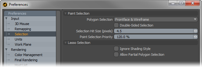
Paint Selection--
Polygon Selection: This option determines the behavior of lasso or paint selection modes when selecting components in the OpenGL viewports.
Frontface & Wireframe- Default behavior is only forward facing polygons are selected, except when in Wireframe mode where both the front and back facing polygons are selected.
Frontface & Backface-
Default behavior is front and back faces are always selected regardless of viewport style.
Frontface only- Default behavior is to select only front facing geometry regardless of viewport style.
Always Raycast- Paint selection does occlusion testing for hit element regardless of shading style. Wireframe view is treated as solid shading view. If the hit element is occluded by polygon on wireframe view, it is not selected.
No Raycast- Paint selection does NOT do occlusion testing for hit element regardless of shading style. Shaded view is treated as wireframe shading view. Even if the hit element is occluded by polygon on shaded view, it is not selected.
Double Sided Selection: When this option is enabled, any polygons tagged with a material that is defined as 'Double Sided', users can then paint select these polygons from their back side. When disabled, users are unable to paint select polygons from the back.
Selection Hit Size: This value determines the area around a selectable (pre-highlighted) element where clicking the mouse will select it. This value is determined as screen size pixel scale.
Point Selection Priority: This is for controlling the multi component selection mode used in tools such as 'Element Move'. When the cursor is close to the corner of polygon, the distances from the cursor to vertex and the connected edges are very close. The 'Point Selection Priority' option gives priority to point selection over edge selection.
Lasso Selection--
Ignore Shading Style: The typical behavior of polygon selection in MODO is to select what is visible to the user, this means that when marquee selecting a sphere in Shaded display style, only the polygons facing the users are selected, but while in Wireframe display style the same selection will select both forward and backward facing polygons (as the rear facing polygons are now visible to the user, therefore selectable). When 'Ignore Shading Style' is enabled MODO's selection mode will work identically regardless of the viewport display style.
Allow Partial Polygons Selection: In order to select a polygon when using the marquee selection style, users will need to completely surround the target with the marquee in order to successfully select the intended geometry. With the 'Allow Partial Polygons Selection' option enabled, all selectable geometry that is intersected by the marquee line, even by a tiny bit, will be selected.
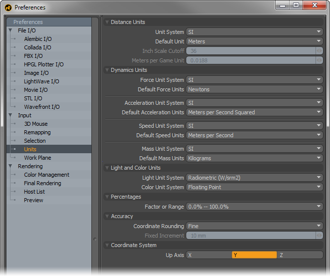
Distance Units--
Unit System: Users can choose their preferred measurement units system based on several options. Once set, this is the measurement input method MODO will use for all numerical input values-
SI- The International System of Measurement (abbreviated 'SI') is the modern form of Metric, complies to universal base units.
Metric- A universal system of measurement based on powers of '10' -millimeter, centimeter, meter, kilometer.
English- A historical measurement system based on Imperial Units -mils, inch, foot, yard and mile
Game Units- An arbitrary unit of measurement (defined by the 'Meters per Game Unit' setting).
Unitless- An arbitrary decimalized unit of measurement based on cubic meters, essentially 1 unit = 1m.
Default Unit: This option is dependent on the 'Unit System' and determines the default unit used when no unit is specified.
Inch Scale Cutoff: When the 'English' Unit System is selected, the 'Inch Scale Cutoff' determines the cutoff where MODO will display strictly inches as feet and inches. For example, when set to the default 36, 27 inches will display as 27", but 42 inches will display as 3' 6".
Meters per Game Unit: When utilizing the arbitrary 'Game Units' systems, users can use this value to determine the scale of a single unit. This allows users to work with even whole numbers. So if a 1m equivalent is really 1.375 real world meters in MODO, users an simply enter 1.375 here and then specify units normally in the numerical input fields.
Dynamic Units--
Force Unit System: This option determines the default Force unit MODO uses when specifying dynamic Force-
Default Force Units: Users can specify alternate units of Force to work with using this control. MODO will default to the selected unit when a unit is not specified in the related input field.
Acceleration Units System: This option determines the default Acceleration unit MODO uses when specifying acceleration-
Default Acceleration Units: Users can specify alternate units of Acceleration to work with using this control. MODO will default to the selected unit when a unit is not specified in the related input field.
Speed Unit System: This option determines the default Speed unit MODO uses when specifying speed (distance traveled over time)-
Default Speed Units: Users can specify alternate units of Speed to work with using this control. MODO will default to the selected unit when a unit is not specified in the related input field.
Mass Units System: This option determines the default unit of Mass MODO uses when specifying an objects Mass-
Default Mass Units: Users can specify alternate units of Mass to work with using this control. MODO will default to the selected unit when a unit is not specified in the related input field.
Light and Color Units--
Light Unit System: This option determines the default Light Unit MODO uses when specifying a lights brightness-
Radiometric- Measurement of the electromagnetic spectrum (which included visible light); defined by power of radiation.
Photometric-
Measurement of brightness of light as perceived by human eye; defined by luminous intensity.
Color Unit System: Determines the color unit system used for specifying colors in MODO-
Floating Point- Determines colors based on decimals, uses 0-1 range (and beyond for HDR colors).
Percentage- Determines colors based on percentages, uses 0%-100% range.
Integer- Determines colors based on 8bit value scale, uses 0-255 range (2 to 8th power = 256 values)
Hexadecimal- A computer numerical system similar to binary represented by 16 characters. 2bit Hex produces 256 values, similar to Integer color units. Widely used in specifying color on the web, uses 00.00.00-ff.ff.ff range.
Percentages--
Factor or Range: This option determines surfacing and material value units, users can specify values as a percentage 0%-100% or as a float value 0.0-1.0
Accuracy--
Coordinate Rounding: This option controls how mouse input is converted, via the Work Plane, into 3D coordinates.
None-- This means that no coordinate rounding is done. Every mouse move gives unclamped coordinates (typically with lots of decimals). This option is basically the raw 2D -> 3D transform. Useful for working freehand.
Normal-- This option attempts to give clean, round coordinates based on the users view transform; so as the mouse moves, users can see values that are nice in your current unit system display in the information tab. The step size will get smaller or larger as the user zooms in or out. Users may need to move the mouse cursor 2-3 pixels to see values update.
Fine-- This option is similar to 'Normal' but optimizes for closer to one step of coordinate rounding from one pixel of mouse movement. Gives the user finer grained input, but can be difficult to hit exact values.
Fixed-- This option uses the 'Fixed Increment' preference to put a lower limit on both coordinate rounding and the grid. If the user sets the fixed increment to 10mm that means the grid will never get finer than 10mm, and all input will be rounded to the nearest 10mm even at high zoom. When zoomed out, however, the grid will show larger values but the step size will always be a multiple of the fixed increment.
Forced Fixed-- This option is similar to 'Fixed', but forces the size of the grid and the input step to match the increment exactly no matter the zoom level.
Fixed Increment: When the Coordinate Rounding is set to either 'Fixed' options, this value determines the Fixed coordinate rounding grid.
Coordinate System--
Up Axis: This option determines the major axis that is considered the default up direction for MODO. 3D programs typically use 'Y' as up, where CAD applications typically use 'Z' as the up direction. When importing geometry, if it is always 90° off, changing the up axis to match the originating application may resolve the issue. This can also be set on a per scene basis in the 'Scene Item'.
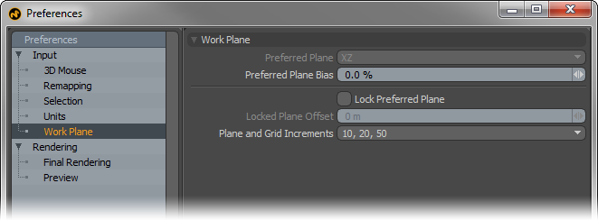
Work Plane--
Users can favor certain planes when using the Work Plane, especially in instances where users don't want to lock the plane, but it would be helpful to have it face a certain direction, such as modeling a rough city, users could rotate the views but keep the Work Plane mostly facing upwards (like it was the ground) when creating new geometry.
Preferred Plane: When the 'Preferred Plane Bias option is set above 0%, uses can choose a preferred Work Plane. Based on the bias amount, MODO will attempt to keep the work plane positioned at the preferred plane determined by its two major axes.
Preferred Plane Bias: When working with the Work Plane, MODO tries to keep the plane perpendicular to the viewport window when navigating and rotating the view. Increasing the Plane Bias option will increase MODO's favor of the Preferred Plane. Setting a very high value means MODO would almost always favor the preferred plane.
Lock Preferred Plane: Users may also prefer to lock the Work Plane to a specific plane facing direction by enabling this option. Once fixed, rotating the viewport will have no effect on the position or angle of the work plane.
Locked Plane Offset: When the Work Plane is locked, users can additionally set an offset (from the origin), providing accurate control over the position and placement of the work plane when used as a construction plane.
Plane and Grid Increments: As users zoom in and out of a scene, the Work Plane grid adjusts the density of the grid divisions adding or removing subdivisions based on the Plane Increments. Users can modify this behavior using this option.