
The Element Move tool provides users with a very fast method for editing individual component elements a mesh (either vertices, edges and polygons). The tool uses the first mouse click to determine the element directly under the mouse. Pre-highlighting of the element will prompt the user which element will actually be transformed when the mouse button is clicked. When over the proper element, users can simply LMB+click drag the mouse to move the element in 3D space, or you can release the mouse button and use the handles to move the element along that axis.
There are two modes for the tool, 'Manual' and 'Automatic'. By default the tool works in Automatic mode which means the element type to be edited is determined at mouse down. If you click on an edge you will edit the edge and if you click on a polygon you will edit the polygon. This allows you to edit components of the mesh independently of the current selection state. The Manual mode forces the tool to act only on the component type defined by the current global selection mask. If selection is set to Vertices and the tool is in manual mode, you will only be able to edit vertices.
The Element Move tool also has a Falloff value which will create a spherical area of influence around the element under the mouse. This value can be set via the properties panel for the tool or by RMB dragging in the 3D viewport. The falloff is represented in the 3D view by a yellow wireframe sphere so you can interactively adjust the region.
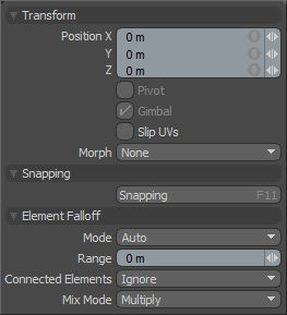 Transform--
Position: When adjusting an object interactively in the viewport, the 'Position' input fields will display the current offset distance applied, providing useful user feedback. Users may use the X,Y and Z input fields to apply specific offset distance values (calculated from position the object was in when the tool was activated).
Pivot: Disabled for the Element Move tool.
Gimbal: Disabled for the Element Move tool.
Slip UVs: (Only in Component Modes) UV values are generally fixed to specific vertices, subsequently further edits to the geometry may warp, deform or otherwise distort the UV values in undesirable ways requiring users to adjust the map or redo it altogether. To avoid this undesirable result, users can enable the 'Slip UVs' function so as to not disturb any existing UV mapping applied to the geometry.
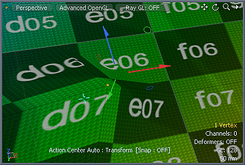 'Slip UVs' function disabled, note texture warping. | 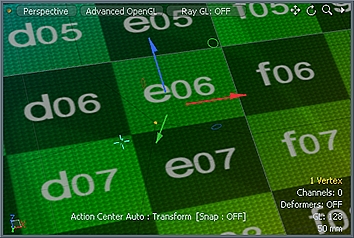 'Slip UVs' function enabled, texture remains even. |
Morph: (Only in Component Modes) The Morph option determines how MODO treats stored Morph information when applying transforms to geometry (Move, Rotate, Scale, etc.). In previous versions of MODO, in order to transform a Morph along with its base, it needed to be selected in the Vertex Map list. If it wasn't, relative Morph map data when recalled would produce distorted, undesirable results. If users were unaware of the requirements, it was easy to accidentally mess up a model. To remedy this problem, there are now three options controlling how the Morph Map vertex data is dealt with when applying any transforms--
None- Unselected Morph data is not affected, though selected (visible) Morphs can still be transformed independent of their source.
Transform- With this option selected, Morph data is transformed along with base mesh.
Keep Positions- With this option Selected, Morph data is converted into a Absolute Morph Map and all vertices retain their pre-transformed positions.
Snapping--
Please reference the 'Snapping' Section of the documentation.
Element Falloff--
Mode: Here users can define the automatic center that the transform offsets from when applied, as well as the element type selected when hovering. 'Auto' is the default and will select whatever element the mouse is over, positioning the center where the mouse pointer intersects the surface it is modifying. Other options allow users finer control.
Range: With the 'Range' setting, users may define a soft falloff region that will attenuated the transform over the ranges distance, defined as a distance.
Connected Elements: Defines what connected geometry will do when an element is transformed.
Ignore-- Ignores all connected elements and only moves the element specified.
Use Connectivity-- Only affects single surface/connected elements, unconnected elements within range will be ignored.
Rigid Connections-- Moves all connected elements equally the specified distance.
Edge Loops-- Moves the connected loop, defined by all the connected quad polygons/edges/vertices in a single row.
Mix Mode: In instances where there are multiple falloffs applied to a transform, the mix mode defines how each interacts with the other.

