

Render Outputs are simply what their name describes, they are the output of a 'Render' operation, and the results of all visible layers of the Shader Tree. Invoking the 'Render' command or pressing 'F9' when no Render Outputs are present and visible will only produce an error message. The 'Effect' of the Render Output layer can be changed as a variety of options. Samples demonstrating each render output, including detailed descriptions of each are available on the secondary Render Outputs page of the documentation listed under the Rendering section.
modo offers many different 'Render Outputs' useful in a variety of situations ranging from purely diagnostic, to having specific compositing utility in an external application. A default scene automatically includes a 'Final Color' and 'Alpha' output which should be fine for most situations. Additional layers can be added from within the Shader Tree viewport itself, by LMB-clicking the 'Add Layer' option of the full viewport window and selecting 'Special > Render Output' from the pop-up menu. This adds an additional layer to the top of the tree. Users may then RMB-click in the 'Effect' column of the shader tree for a pop-up context menu that allows one to select alternate output types. Render Outputs can be enabled either via the layer 'Enable' checkbox within the properties viewport, or by clicking the eyeball icon in the visibility column of the Shader Tree. All enabled outputs are rendered simultaneously each time the 'Render' or 'Render Animation' commands are invoked. Once rendered the individual outputs appear in the Render Display window and are accessible from the layer menu therein.
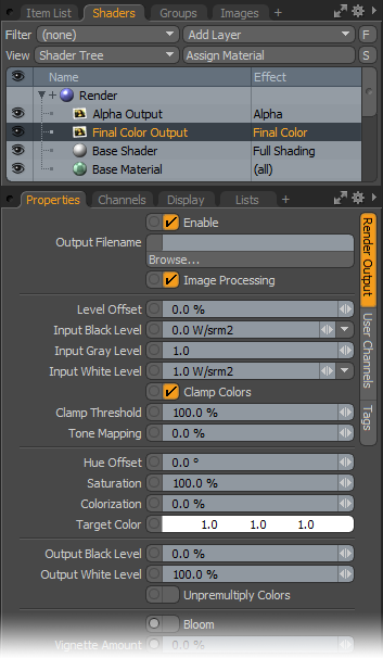
Selecting any of the 'Render Outputs' within the 'Shader Tree' makes their editable attributes available within the 'Properties' viewport. Selected layers are indicated by the dark bar highlighting the layer name. All Render Outputs share the same set of attributes, with 'Ambient Occlusion', 'Depth', 'Final Color' and 'Motion Vector' having additional option covered below.
 Layer--
Enable: The 'Layer Enable' checkbox allows the user to temporarily enable/disable a layer without losing stored values. Disabled layers are saved with the scene file. Render Output--
Output Filename: This function allows the user to specify a filename and location for the saving of a rendered animation. Click the 'Browse' button to open the 'File Save' dialog box. Specify a name and location for the rendered output. Images will be saved the next time the user invokes the 'Render Animation' command from the menu bar. Additional automatic output naming options can be specified in the 'Frame' settings of the Render item as well. Note that Rendering scenes using the 'Render' command or 'F9' do not save the image automatically to disc, but merely displays the rendered result in the 'Render Display' window, for that use the 'Save As' option of the Render Display window.
Image Processing: Users can toggle this option to control the post processing applied to the rendered image. When enabled post processing functions will apply to the rendered output, when disabled post processing settings will be disregarded. Post processing can be a powerful way to adjust the final rendered image, this options makes it easy for users to quickly see to what degree the image processing is contributing to the final render without disabling all the settings individually.
Level Offset: The 'Level Offset' option slides all color values up or down the value scale, shifting them identical amounts in the rendered image. For example, if an image had a 0% black pixel and a 50% gray pixel, offsetting the values 50% would result in the black pixel changing to 50% gray and the gray pixel changing to 100% white with all other values changing corresponding amounts.
Input Black Level: The 'Input Black Level' control specifies the radiance or luminance level that corresponds to pure black in the final rendered image (a pixel color value of o.0). To use the input level controls effectively, 'Clamp Colors' must be disabled.
Input Gray Level: The 'Input Gray Level' is a non-linear luminance adjustment that applies a curve-like function to the pixels, modifying the mid-range the most while attenuating the adjustment amount for values moving toward the defined 'Black' and 'White' points. Values above 1.0 will lighten the midrange while values below 1.0 will darken the midrange.
Input White Level: The 'Input White Level' control specifies the radiance or luminance level that corresponds to pure white in the final rendered image (a pixel color value of 1.0). To use the input level controls effectively, 'Clamp Colors' must be disabled.
Clamp Colors: The "Clamp Colors" option will suppress all color values in a rendered image to truncated 24 bit values prior to anti-aliasing producing cleaner result in areas of extreme contrast. However, when this setting is enabled, you will lose any extended dynamic range present in the image (making proper tone mapping impossible). If you intend to save your image in an high dynamic range format, leave the setting disabled. Additionally, instance where 'Tone Mapping' may not be appropriate, any apparent blockiness can be minimized by adding a small amount of 'Bloom', available as an option of the 'Final Color' output. When enabled, a small amount of dithering is added to reduce or eliminate banding in gradations.
Clamp Threshold: Determines the threshold within the image where clamping takes place.
Tone Mapping: Dynamic Range is measured as the difference between the darkest shadow to the brightest highlight in an image. Most image formats dynamic range pale in comparison to that of the world around us. Much in the same way that a photographer struggles to capture all of the range our eyes can see using a camera, you may find your renders have shadow areas that are too dark, and highlight areas that are too bright. Luckily, modo renders in full floating point accuracy, providing dynamic range well beyond what your monitor is capable of displaying. This allows users to modify the overall tonal balance of the rendered image in several ways, including 'Tone Mapping', a technique that is used to compress the rendered dynamic range into something viewable; shadows will open revealing previously obscured details as will highlights. To use the 'Tone Mapping' function, 'Clamp Colors' must be disabled. You will often find it takes a combination of settings for White Level, Tone Mapping and Gamma to achieve the best results, please reference the 'Tone Mapping' page of the documentation for further examples.
Hue Offset: The 'Hue Offset' option will adjust the color values of the rendered image independently of the luminosity or brightness values, shifting them across the entire spectrum in a sequential fashion, for example when shifting a red color, moving the values in a positive fashion will adjust reds toward an orange hue, then yellow and so on. The hue values should be thought of like a wheel, where a rotation of 180° inverts all the color values and a rotation of 360° brings them back to their initial state.
Saturation: The 'Saturation' options controls the concentration or amount of color in an image independent of the luminosity of brightness. At 100%, colors will be fully saturated as defined in the items material settings, reducing the value will reduce the overall color saturation down to a value of 0% producing an image only with gray shades. Since modo renders in full 32bit floating point accuracy, values above 100% will increase saturation without introducing the color banding and artifacts generally associated with over-saturating images.
Colorization: Users can use the 'Colorization' options to introduce an overall color tint into an image. This can be purely for artistic reasons but can also be helpful in reversing color casts introduced by Image Based Lighting among other things. Users need only to define a color with which to tint by setting a 'Target Color' and then adjusting the 'Colorization' amount determining the strength of the color into the image. A value of 0% produces no colorization attenuating toward 100% where the image is replaced fully by the target color.
Target Color: This value determines the color with which to tint the rendered image when the Colorization option is above 0%.
Output Black Level: This value determines the output value of what is considered fully black in the image. Adjusting the value upwards changes the Black point to a shade of gray. As values are adjust, intermediate values between black and white are adjusted as well.
Output White Level: This value determines the output value of what is considered fully white in the image. Adjusting the value downwards changes the White point to a shade of gray. As values are adjust, intermediate values between white and black are adjusted as well.
Unpremultiply Colors: When generating pixel values in rendered images, modo 'multiplies' the rendered result with the background color to calculate the final result. This 'multiplied' final result is fine for most cases, however, when using alpha channels to composite multiple images together, partially transparent pixels will often exhibit halos, an artifact of the previous background color. 'Unpremultiply' basically reverses this effect. Activating this option won't reveal any difference in modo's render display, you'll need to save the image and open it in an another application to see the result. This function requires that the object/scene is rendered over a solid black background with a corresponding alpha channel. This can be easily achieved by disabling the 'Visible to Camera' option in the 'Environment' Item (and the 'Visible to Refraction Rays' option in cases where there are transparent surface, note that this will affect how the render looks).
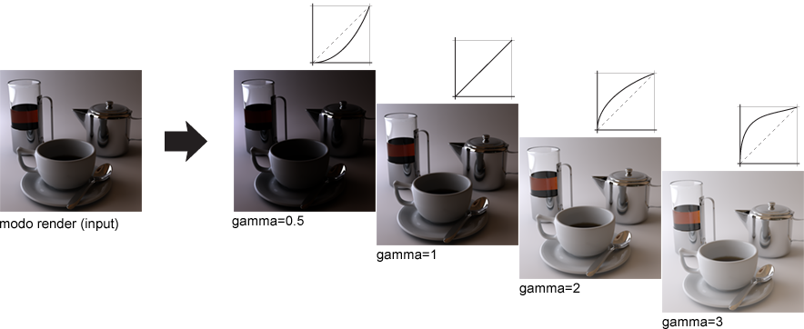
Output Gamma: Gamma is the measure of total contrast in an image and represents the relationship of an image input to an image output. In this case, the 'input' is modo's rendered image; what modo is holding in its memory and the 'output' is either the image being displayed in the 'Render Display' viewport (what you see) or the image that is saved. A gamma value of 1 is said to be 'linear', what modo rendered, is identical to what is displayed. Modifying the 'Gamma' value changes how the image is represented. Values higher than 1 lighten the image, while values lower than 1 darken it. Adjustments to the gamma value are not linear, i.e. they don't change all the pixels in an image the same amount, explaining why it is often referred to as a gamma curve. The default Gamma value is derived from the global preference found in the Preference Editor under 'Rendering'. Adjusting this Render Output 'Gamma' value overrides the global preference on a per item layer basis.
To separate the gamma of the 'Render Display' window from that of the saved file, open the Preferences window from the menu bar 'System > Preferences' and select the 'Rendering' options. By activating “Independent Display Gamma†you can set a gamma correction that will only apply to the image as it is viewed in the Render window. The saved image data will always use the Output Gamma value found on the Render Output in the shader tree.
Gamma is a complex matter in rendering, especially when maintaining consistent colors across a variety of applications as an image travels through a projects pipeline. Comprehensive coverage of the topic is beyond the scope of this document, but there have been numerous helpful threads at the Luxology Forum ![]() that cover the topic well. An internet search is certain to provide additional useful results.
that cover the topic well. An internet search is certain to provide additional useful results.

TIP: Since a render output is just another layer, it can reside anywhere in the shader tree. Typically they are at the top directly under 'Render' item, as this is where they see the result of all layers in the tree, but if a 'Render Output' is placed inside of a Material Group, the Render Output will only 'render' what it sees within that group, this makes it possible to render alpha channels for specific items based on a polygon tag, instead of making some item specific shader or hiding items in the item list. All active 'Render Outputs' will render each time the render command is invoked, and will appear within the layer menu of the Render Display viewport.
Ambient Occlusion
The 'Ambient Occlusion' output generates an occlusion map where occluded areas; crevices and other inaccessible areas of a scene shade darker, while open areas render lighter colors, approximating an overall global illumination type of shading. Grainy renders can be smoothed out by increasing the 'Occlusion Rays' value, controlling the density of the occluded areas is done through the 'Occlusion Range'.
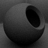
Occlusion Rays: The 'Occlusion Rays' setting specifies the number of random rays modo shoots out from a surface when shading a pixel for Ambient Occlusion. Generally, the higher the number of rays, the more accurate (and smoother) the AO image will be, low numbers introduce noise as variations in neighboring pixels become more evident.
 Occlusion Rays 32 | 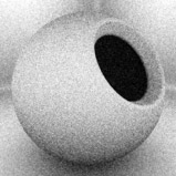 Occlusion Rays 64 |  Occlusion Rays 128 |  Occlusion Rays 256 |  Occlusion Rays 512 |
Occlusion Range: The 'Occlusion Range' settings specifies the length of the rays that are fired from a surface. If you have a complex object with overlapping elements, limiting the ray range is a good way to control what recessed areas are shaded darker, it also helps to push the shading further into recessed areas. A value of 0m disables the range defaulting the value to the maximum length of the scenes overall bounding box size.
 Range 0m (disabled) | 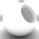 Range 50mm | 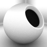 Range 100mm |  Range 150mm | 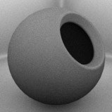 Range 200mm |
Depth
The 'Depth' output generates a Z-Buffer that represents the distance from the camera to the geometric surface in shades of gray. Rays begin white at the ray origin (camera position) and attenuate darker as they get longer becoming fully black at the specified 'Maximum Depth' value. Useful for calculating Depth of Field in an external application or for composing a fog effect into a rendered scene.
Maximum Depth: The Maximum Depth value sets a "clipping plane" for the black point so that modo knows at what distance to shade the Z-buffer pure black.
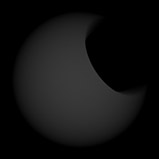 Depth 100mm | 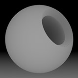 Depth 200mm | 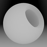 Depth 300mm | 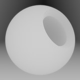 Depth 400mm | 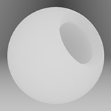 Depth 500mm |
Final Color
The 'Final Color' output represents the settings of the shader tree, leveraging all visible material and texture layers as well as shaders and the render item settings.
Bloom: In photography, when a very bright part of an image neighbors a very dark part, the bright part will appear to glow, this phenomenon is known as Bloom. modo's 'Bloom' simulates this effect by removing excess energy from a pixel and distributes it around to its neighbors. This checkbox enables the effect, once checked, two additional options become available-
Bloom Threshold: The 'Bloom Threshold' sets the lower threshold to which pixel are effected by 'Bloom'. When set to 100%, only the very hottest specular highlights will bloom, where at 0% every pixel in the scene will receive the bloom effect.
 Bloom Threshold 0% |  Bloom Threshold 25% |  Bloom Threshold 50% |  Bloom Threshold 75% |  Bloom Threshold 100% |
Bloom Radius: The 'Bloom Radius' sets the distance that energy is distributed, in effect controlling the size of the glow. 2% is the default value. Larger radius' impart and ethereal look to the rendered image.
 Bloom Radius 1% |  Bloom Radius 2% |  Bloom Radius 4% |  Bloom Radius 8% |  Bloom Radius 16% |
Vignette Amount: In photography, vignetting is natural reduction of an images brightness toward the outer edges of the frame. The 'Vignette Amount' in modo, when set at 100% is a physically accurate vignette simulation, based on the Cameras Focal Length and Film Size. Values above 100% will darken the resulting vignette, and values below 100% will reduce its visibility.
Contours: modo can render a contour outline around specified boundaries. The options available are-
None- The default value, renders no contouring outline.
Surface Boundaries- Contour line renders around all surface boundary definitions (modo Material tag boundaries).
Segment Boundaries-
Contour line renders around all segment boundary definitions (modo Segment ID boundaries, which are not user definable).
Contour Color: Defines the color of the contour outline using the standard modo color controls for specifying an R, G and B value.
Contour Width: Defines the thickness of the contour line applied to the render output, defined as a pixels, so a value of 1 would render a line 1 pixel wide over all the boundaries.
Fade with Distance: Users can fade the application of the contour outline when enabling this option. Once enabled, an additional option 'Fade Start Distance' determines where the fading effect will start.
Crease Threshold: Determines the angle at which modo draws a contour line. Lower angles generate more lines.
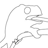 Crease Threshold 180° | 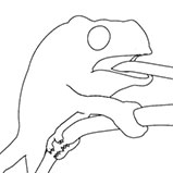 Crease Threshold 90° | 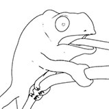 Crease Threshold 45° | 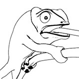 Crease Threshold 15° |  Crease Threshold 5° |
Motion Vector
The 'Motion Vector' output represents the speed and direction at which an item is moving within the scene, calculated per-pixel. The main use of this render output is to apply a post motion-blur effect to the frame using an external compositing application. As rendering actual motion blur in modo requires a fair number of antialiasing passes for a smooth result, rendering out a frame normally and applying the effect separately will achieve similar results in a fraction of the time.
Remap Pixel Values: The 'Remap Pixel Values' option adjusts the resulting motion vector values to values appropriate to low dynamic range images, scaling values appropriately based on the 'Maximum Motion' value. This is typically the desired result. Enabling this option means the values will be remapped, and disabling it means the values will be saved at their actual calculated result (which requires a floating point image format when saving).
Maximum Motion: The 'Maximum Motion' value represents the maximum distance a blurred pixel would travel. This setting also defines the amount of scaling applied to the resulting values when 'Remap Pixel Values' is enabled. When working with the Re:vision ReelSmart Motion Blur tool, you will want to make sure that 'Remap Pixel Values' is enabled, and make sure the 'Maximum Motion' values match in both locations for the proper result.

