
The 'Render Display' window provides users a variety of useful options and feedback for working with the resulting rendered pixels for any modo scene. The Render Display window opens automatically when invoking any of the Render commands, either by keyboard shortcut or through the menu bar. Users may also recall the window without rendering any pixels with the command "Render > Open Render Window". Once open, the window provides a view of the rendered scene, along with a number of useful statistics, comparing tools and image adjustment controls for fine tuning an image. The window is broken into four main areas that are all inter-related -Image Display, Control panels, Render Browser and the Network View (minimized by default). Each section is documented below.
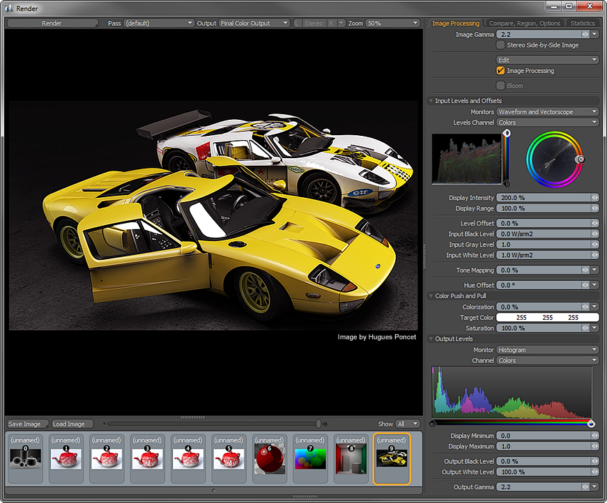
The main area is the actual image display itself. This does duty as both a final image display and provides useful visual feedback to the progression of the rendering frame. Directly above this window are the controls that determine what is actually displayed, such as a particular Render Pass or Render Output to display during rendering, stereo image display options and a zoom level control. Users may also zoom in the window directly using the 'Ctrl+Alt+LMB click and drag. Once zoomed in, use the LMB+click and drag to navigate across the image. Pressing 'Ctrl+A' will fit the entire image to the viewable area.
The Control panel is organized into three tabs, each with a dedicated function. Users can LMB+click on any of the tabs to view the associated attributes. Going left to right, the first tab is the 'Image Processing' panel which provides scores of non-destructive controls to adjust, correct and tone the rendered image. The second is 'Compare, Region Options' which provides tools for rendering limited regions and comparing subsequent and prior renders. The third and last tab is the 'Statistics' panel, which provides useful information regarding the frame during rendering, such as memory usage, elapsed time and the final numbers of polygons; updated live throughout the render process.
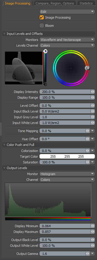 Image Processing--
The 'Image Processing' section provides all the controls necessary to tweak
the look of the final rendered image coupled with advanced visualizers, users can avoid most trips to an external image editor, best of all, its done non-destructively. When adjusting the values in the panel, the Image Display updates providing real time feedback to the changes making it easy to experiment and try different combinations.
Edit: The 'Edit' menu provides some options for moving image processing settings between the Render Output and the Render Display window.
Copy From Scene- If adjustments we're made to the Render Output options after the rendered image is complete, the 'Copy from Scene' option will grab those settings, updating the options of the Render Display window to match.
Paste to Scene- Any adjustments made to the rendered image within the Render Display window will not apply to subsequent renders, as the Render Display window reverts to the settings of the 'Render Item'. The 'Paste to Scene' option copies the settings to the Render Output back to the scene, applying it to all subsequent renders.
Reset- The 'Reset' option returns all image adjustment options to their default values.
Image Processing: The 'Image Processing' toggle disables/enables the application of all the image adjustments options in the Render Display window only, especially useful in seeing the effects of the applied adjustments.
Bloom: In photography, when a very bright part of an image neighbors a very dark part, the bright part will appear to glow, this phenomenon is known as Bloom. modo's 'Bloom' simulates this effect by removing excess energy from a pixel and distributes it around to its neighbors. This checkbox enables the effect, once checked, two additional options become available. Values can be adjusted, providing near real-time feedback in the Render Display window-
Bloom Threshold: The 'Bloom Threshold' sets the lower threshold to which pixel are effected by 'Bloom'. When set to 100%, only the very hottest specular highlights will bloom, where at 0% every pixel in the scene will receive the bloom effect. (examples are found in the Render Output page of the documentation)
Bloom Radius: The 'Bloom Radius' sets the distance that energy is distributed, in effect controlling the size of the glow. 2% is the default value. Larger radius' impart and ethereal look to the rendered image. (examples are found in the Render Output page of the documentation)
Input Levels and Offsets--
Monitors: Several types of feedback displays are offered providing users with a means to analyze values in an impartial way when making adjustments-
Waveform- Displays the amount of energy at each intensity level as a series of vertical strips. Especially useful for detecting crushed shadows or blown out highlights across a wide area of an image, or for checking how evenly the overall tonal range is used in a given image.
Vectorscope- Displays the amount of energy across the hue and saturation spectrum within a unit circle of colors. Especially useful for checking overall color balance or to examine the amount of saturation for a given range of color.
Hue & Saturation Parade- A side-by-side variation of the 'Waveform' display, but for the amount of energy in hue or saturation instead of overall intensity.
Level Channel: The 'Level Channel' option allows users to choose which particular channel information contributes to the monitor displays. Entire images (Colors), or individual channels (Red, Green & Blue), or image brightness information (Luminosity).
Display Intensity: Display Intensity multiplies the displayed brightness of the monitor to make it easier to view intensity levels for under-sampled areas of the image.
Display Range: The 'Display Range' option allows users to set the range of the monitor(s) to values other than the default 0 to 1 range.
Level Offset: The 'Level Offset' option slides all color values up or down the value scale, shifting them identical amounts in the rendered image. For example, if an image had a 0% black pixel and a 50% gray pixel, offsetting the values 50% would result in the black pixel changing to 50% gray and the gray pixel changing to 100% white with all other values changing corresponding amounts.
Input Black Level: The 'Input Black Level' control specifies the radiance or luminance level that corresponds to pure black in the final rendered image (a pixel color value of 0.0). To use the input level controls effectively, 'Clamp Colors' must be disabled.
Input Gray Level: The 'Input Gray Level' is a non-linear luminance adjustment that applies a curve-like function to the pixels, modifying the mid-range the most while attenuating the adjustment amount for values moving toward the defined 'Black' and 'White' points. Values above 1.0 will lighten the midrange while values below 1.0 will darken the midrange.
Input White Level: The 'Input White Level' control specifies the radiance or luminance level that corresponds to pure white in the final rendered image (a pixel color value of 1.0). To use the input level controls effectively, 'Clamp Colors' must be disabled.
Tone Mapping: Dynamic Range is measured as the difference between the darkest shadow to the brightest highlight in an image. Most image formats dynamic range pale in comparison to that of the world around us. Much in the same way that a photographer struggles to capture all of the range our eyes can see using a camera, you may find your renders have shadow areas that are too dark, and highlight areas that are too bright. Luckily, modo renders in full floating point accuracy, providing dynamic range well beyond what any monitor is capable of displaying. This allows users to modify the overall tonal balance of the rendered image in several ways, including 'Tone Mapping', a technique that is used to compress the rendered dynamic range into something viewable; shadows will open revealing previously obscured details as will highlights. To use the 'Tone Mapping' function, 'Clamp Colors' must be disabled. You will often find it takes a combination of settings for White Level, Tone Mapping and Gamma to achieve the best results, please reference the 'Tone Mapping' page of the documentation for further examples.
Hue Offset: The 'Hue Offset' option will adjust the color values of the rendered image independently of the luminosity or brightness values, shifting them across the entire spectrum in a sequential fashion, for example when shifting a red color, moving the values in a positive fashion will adjust reds toward an orange hue, then yellow and so on. The hue values should be thought of like a wheel, where a rotation of 180° inverts all the color values and a rotation of 360° brings them back to their initial state.
Color Push and Pull--
Colorization: Users can use the 'Colorization' options to introduce an overall color tint into an image. This can be purely for artistic reasons but can also be helpful in reversing color casts introduced by Image Based Lighting among other things. Users need only to define a color with which to tint by setting a 'Target Color' and then adjusting the 'Colorization' amount determining the strength of the color into the image. A value of 0% produces no colorization attenuating toward 100% where the image is replaced fully by the target color.
Target Color: This value determines the color with which to tint the rendered image when the Colorization option is above 0%.
Saturation: The 'Saturation' options controls the concentration or amount of color in an image independent of the luminosity of brightness. At 100%, colors will be fully saturated as defined in the items material settings, reducing the value will reduce the overall color saturation down to a value of 0% producing an image only with gray shades. Since modo renders in full 32bit floating point accuracy, values above 100% will increase saturation without introducing the color banding and artifacts generally associated with oversaturating images.
Output Levels--
Monitor:
Histogram- A Histogram is a graphical display that shows the distribution of values across the spectrum of the image. Think of it like a graph of how many values each individual shade has, useful in subjectively determining wether an image is neutral, low key, high contrast or otherwise.
RGB Parade- Where the 'Histogram' shows overlays of individual channels the 'RGB Parade' shows each individual R, G and B channel side by side, proving a clearer view of each channels individual contribution to the final image.
Channel: The 'Channel' option allows users to choose which particular channel information contributes to the monitors display. Entire images (Colors), combination of all or individual channels (RGB, Red, Green & Blue), or image brightness information (Luminosity).
Display Minimum/Maximum: The 'Display Min/Max' option allows users to set the range of the monitor to values other than the default 0 to 1 range.
Output Black Level: This value determines the output value of what is considered fully black in the image. Adjusting the value upwards changes the Black point to a shade of gray. As values are adjust, intermediate values between black and white are adjusted as well.
Output White Level: This value determines the output value of what is considered fully white in the image. Adjusting the value downwards changes the White point to a shade of gray. As values are adjust, intermediate values between white and black are adjusted as well.
Output Gamma: Gamma is the measure of total contrast in an image and represents the relationship of an image input to an image output. In this case, the 'input' is modo's rendered image; what modo is holding in its memory buffer and the 'output' is either the image being displayed in the 'Render Display' window (what you see) or the image that is saved. A gamma value of 1 is said to be 'linear', what modo rendered, is identical to what is displayed. Modifying the 'Gamma' value changes how the image is represented. Values higher than 1 lighten the image, while values lower than 1 darken it. Adjustments to the gamma value are not linear, i.e. they don't change all the pixels in an image the same amount, explaining why it is often referred to as a gamma curve. The default Gamma value is derived from the global preference found in the Preference Editor under 'Render'. Adjusting this Render Output 'Gamma' value overrides the global preference on a per render buffer basis.
To separate the gamma of the 'Render Display' window from that of the saved file, open the Preferences window from the menu bar 'System > Preferences' and select the 'Rendering' options. By activating "Independent Display Gamma" you can set a gamma correction that will only apply to the image as it is viewed in the Render window. The saved image data will always use the Output Gamma value found on the Render Output in the shader tree.
Compare, Region, Options
 Compare--
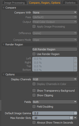
The Compare options provide users the ability to
examine two images in a variety of ways, making it easier to contrast any differences between them.
Compare with: The 'Compare with' option determines what opposing images are compared-
None- No image comparison
"B" Slot- Two separate images are compared, 'Slot A' is determined by the current image selected in the browser, 'Slot B' is determined by holding down the 'Ctrl' key and LMB+clicking on a second image slot in the browser. A small 'A' and 'B' icon will appear beneath each image signifying which is which.
"A" Slot Output- With this option, users can compare between associated 'Passes' or 'Render Outputs' of the same image.
Pass: When the '"A" Slot Output' option is selected, users can determine which particular 'Pass' output to compare against with this option.
Output: When the '"A" Slot Output' option is selected, users can determine which particular 'Render Output' to compare against with this option.
Apply Image Processing: The 'Apply Image Processing' toggle disables/enables the application of all the image adjustments options in the Render Display window.
Difference:
Compare Mode: Several modes define how the two images are compared, each with additional options-
Wipe- Two images are overlaid and the top image is wiped away revealing the lower image. Additional options allow users to select 'Horizontal' or 'Vertical' wiping directions and set a position percent, or choose the 'Dissolve' option and set an 'Opacity' amount.
Spotlight- The 'Spotlight' option reveals the "B" images as a circle around the mouse pointer (move the mouse over the image to see its results) . The size of the circle is determined by the 'Spotlight Radius' control.
Side by Side- The 'Side by Side' options displays two half width images that can be scrolled with an option to Stack the images vertically.
Render Region--
The 'Render Region' option allows users to selectively render a smaller segment of the entire image making the iterative process of creating a final rendered image faster and more fluid. For user's convenience, these settings duplicate the functionality of the Render items Render Region functionary.
Edit Render Region: When this option is enabled, users can drag directly over the rendered image to define the limited region area interactively. Subsequently, once the initial area is defined, edges and corners of the region will highlight allowing further refinement to the defined region. LMB+click and drag the highlighted border to adjust.
If edits are being made to the same scene, the area outside the defined region will be used as a background to successive renders until disabled. When switching between scenes or image resolutions, then the background area outside the region will simply render as black.
Use Render Region: The 'Use Render Region' option toggle will temporarily enable/disable the limited region functionality without losing any of the settings.
Left/Right/Top/Bottom: Left/Right and Top/Bottom percentage settings work in conjunction with each other to specify the total rendered region width and height.
Options--
Display Channels: All resulting rendered images are generated as standard RGB bitmap format images. For diagnostic purposes, it may be valuable for users to see the individual 'Red, 'Green' or 'Blue' color channels of an image.
Display Channels in Color: When this option is enabled, individual channels will display as colored versions of themselves. When disabled, individual channels will display as grayscale representations.
Show Transparency Background: When enabled, any loaded images that contain an alpha/transparency channel will display a grey checkerboard where the image is transparent mimicking a similar option found in many image editing applications. Note that this option doesn't apply to internally rendered alpha channels.
Show Clipping: When enabled, a diagonal black and white stripe pattern (called a Zebra pattern) will display over overexposed or blown out areas of the image providing useful feedback for adjusting image white point and tone mapping an image to compress as much dynamic range information as possible.
Fields: For scanline televisions (older tube televisions) there were originally two half frames that made up each whole frame, interlaced on top of each other to make a single image. Enabling the 'Field Rendering' option will properly render two discreet moments in time and interlace the resulting half-frames into a single image (in essence doubling the frame rate). The 'Fields' option allows users to independently display either the 'Upper' or 'Lower' field, or 'Both' which is the standard default for non-interlaced (progressive) frames.
Field Doubling: When viewing individual fields, enabling the 'Field Doubling' option will duplicate every other line eliminating the black screen lines from the display.
Default Image Gamma: When loading non-HDR image formats into the Image Browser, this is the default gamma value applied to the imported image. For more information on gamma, please reference the Render Output page of the documentation.
Max Render Slots: This value determines the maximum number of frame buffers (renders) saved on disc in the Image Browser. Once this value is exceeded, the oldest render will be deleted, unless locked. If all frames are locked, then they will be treated as if all unlocked once the maximum number is met. This option is not affected by images loaded into the Browser.
Always Show Time in Seconds: Displays time in total seconds instead of HH:MM:SS, example- 01:12:37 would be displayed as 4357 seconds.
Statistics
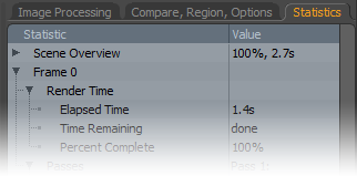 The Statistics panel provides a huge amount of statistical information related to rendering the scene. Included in this information is the elapsed time as well as an approximate remaining time for in-progress frames. For finished frames, the total rendering calculation time is displayed, along with total memory usage, total number of polygons generated. The information is cleanly organized and largely self explanatory. Navigation of the list works the same as other viewports. Users can open or close a specific section by LMB+clicking the preceding arrow (
 ![]() ). Holding shift and clicking an arrow will open/close all sub-sections of the clicked on topic, making it easy to view all the information related to a single frame.
). Holding shift and clicking an arrow will open/close all sub-sections of the clicked on topic, making it easy to view all the information related to a single frame.
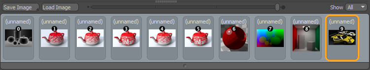
The Render Browser allows for an unlimited number of rendered frames (well, it is limited by the amount of hard drive space available). The browser itself serves a couple of purposes, foremost being that users can select the current image to be displayed in the display area by LMB+clicking on any of the icons. The current image selection is designated by the orange outline of the icon; only the current image can be modified using the image adjustment controls. The render order of images is also displayed using the small number icons above each image. When the mouse hovers over an icon, two additional controls appear, an 'X' that if clicked will remove the image from the browser (deleting it from disc) and a small lock icon users can click to lock items from being deleted accidentally. Simply click the lock icon again to unlock. Users can select multiple images by holding down the Ctrl' key as well allowing for gang removal/locking/unlocking of multiple images.
The Render Browser is also used to Load and Save images. When images are rendered, their existence in the Render Display is kind of in limbo, as the images are visible can be viewed and modified in the Render Display, but they can't be accessed outside of the display and therefore will need to be saved. Using the 'Save Image' button directly above the browser allows users to define a format and location for the image. Please reference the 'Saving Images' page of the documentation for more information concerning images and formats.
Additionally, images can be loaded into the browser area, which is very helpful for when users wish to apply image adjustments, or use previous renders to compare a current render from when the render buffer no longer exists. To load an image, LMB+click the 'Load Image' button above the browser area, opening an OS specific window. There, users may navigate to the stored image location, select the target file, and press 'Open' to load the file into the browser. If any modifications are applied to the file, it must be saved again to retain the settings.
Below the Render Browser area is a minimized 'Network View' panel. Users may open the panel by LMB+clicking and dragging upward on the small group of tiny squares, revealing the panel. This viewport indicates the number of cores available on each machine, machine name, user name, mode, status and message. Further, you can tell if a machine is connected to your active host by the color of the text. Green text indicates that the machine is connected and ready for rendering. Black indicates systems that are connected, but not enabled as slaves. Any other color indicates a problem with the connection or availability.

