
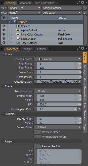
The 'Render' Item always occupies the top spot in the shader tree, this is no mistake considering its importance. The Render item can be thought of as a general container for global scene render settings. When the Render item is selected, its various attributes become available in the Properties viewport. It is broken into three sub tabs of related settings. The 'Frame' tab allows users to adjust render settings specific to the rendered frame itself such as its dimensions. The 'Settings' tab allows users to adjust render settings specific to rendering quality such as anti-aliasing. The 'Global illumination' tab allows users to adjust render settings specific to Global Illumination, a rendering technique that utilizes bounced light to produce incredibly realistic rendered images.
Frame
 Render--
Render Camera: The 'Render Camera' popup option allows the user to select a specific camera from which the rendered image will be created. While a basic modo project begins with a single default camera, additional cameras may be added within the Item List by using the 'Add Item' button of the Items List and selecting 'Camera'. These cameras, like any item in the mesh list, can be renamed by RMB-clicking and choosing Rename. By default each new camera is assigned a numeric differentiator such as Camera(2), Camera(3) etc. Once additional cameras have been added to a project the Render Camera popup can be used to select them. Additionally, the current camera can be animated to switch to different views during a sequence or alternates selected for individual Render Passes.
Frame Range: In animated scenes, the frame range specifies the sequence of frames that will render when you use the 'Render Animation' command. The top number specifies the first frame rendered, while the lower number specifies the last frame that will render.
Frame Step: When rendering out animated sequences, the frame step value will skip the specified number of frames. Essential for testing rendered sequences, rendering with a frame step of 2 (every other frame) would cut the overall render time in half, a frame step of 4 (every fourth frame) would cut the overall render time by three quarters and so on, while still giving a good idea of the final animated scene albeit at a lower frame rate. This function is relative to the Frame range. If you specify frame 7 as your first frame with a step of 2, frames 7,9,11,13 and so on would be rendered.
Frame Passes: The 'Frame Passes' option controls how many times a single frame is rendered (Not to be confused with 'Render Passes' which are entirely different). The results of each pass are evenly blended to make up the final frame. The random numbers used to generate fur are varied for each pass, so the resulting blended fur will look softer. If motion blur is enabled, then each frame pass will cover just part of the exposure. For example, if there are four frame passes then the first pass will cover the first quarter of the interval from shutter open to shutter close. Increasing this value above '1' will increase render times significantly, so unless users are in need to softer fur or higher quality motion blur, there is no added benefit to increasing this value.
Output Pattern: These pattern options provide users a means to automatically name files when saving rendered animations, as either flat images or layered images. Instructions appear in the "< >" brackets, and those in the "[ ]" square brackets are ignored in instances that don't apply.
<LR> adds an 'L' for Left or an 'R' for Right when rendering stereo images.
<output> names file for render output item
<pass> names the file for the render pass
<F> Frame number (add extra 'F' for extra leading zeros).
So in practice, you could put Robot_[<LR>]_<pass>_<FFFF> and the resulting file name for the left render of the 'BG' named render pass would be "Robot_L_BG_0001.exr".
Frame--
Resolution Unit: This popup allows you to select how the rendered frame's image size is specified, either as pixels, or as inches.
Frame Width/Height: With Frame 'Width' and 'Height', the user can specify the size of the frame rendered when you invoke the 'Render' command. Dependant upon the resolution unit, if 'Pixels' is selected, then you can specify the size in pixel units, or if 'Inches' is specified, the user can specify the printed resolution of the rendered image in inches. When set to 'Inches', the DPI setting is used to determine the number of pixels rendered. The typical video size of 640 pixels by 480 pixels is the default size.
DPI: The DPI input field allows the user to directly determine the number of "Dots Per Inch". This is particularly useful when defining image height and width using the 'Inches' resolution unit, as it will be used to determine the final pixel resolution of the rendered images. It will also be added to files on export determining the eventual printed size of the image.
Pixel Aspect Ratio: Most computer screens, by default, use a 'Pixel Aspect Ratio' of 1 which yields "square pixels", what most people are used to. However, some target media use non-square pixels to display images such as NTSC television (0.90). Use this setting to properly render the image for its intended destination. Note: modo will still display the image as if they were square pixels, so rendered images will look squashed/stretched depending on this setting.
Buckets--
Bucket Width/Height: The bucket size defines the number of pixel values calculated concurrently and is controlled via the Height and Width settings. The default value of 32 by 32 means that each bucket will be 32 pixels wide and 32 pixels high. Using larger buckets will increase the amount of memory required but can result in speed improvement. However, if multiple threads are being used it is important to remember that using smaller buckets can result in a better load balanced total frame. It is likely that when using multiple buckets they will not finish at exactly the same instant therefore there will usually be one bucket/thread computing when the other bucket(s)/thread(s) are finished. If the buckets are very large the amount of time the render engine is using only one thread will increase which of course decreases the impact of the additional processors on final render time. One might come to the conclusion that they should set the bucket size as small as possible, this is incorrect as well, system performance may decrease with the overhead to manage the buckets, while reducing anti-aliasing quality (as bucket borders cannot be anti-aliased to their neighboring pixels outside the bucket; decreasing the size of the bucket increases the number of 'border buckets'). Luxology Chief Scientist Allen Hastings, concludes that the 32 by 32 pixel bucket is typically the ideal size bucket when rendering approximately video resolution sized frames.
Bucket Order: The bucket order determines the pattern in which the buckets are rendered. In some cases there can be a small performance benefit to certain patterns. In particular the Hilbert pattern is designed to maximize bucket edge concurrency to reduce the amount of data that must be purged and loaded whereas Random would be most likely the least efficient in that regard. Aside from some slight variance in performance, using different bucket orders is simply entertaining and can be used to impress your friends who use rendering engines with boring fixed render patterns.
Rows-- Renders the buckets in rows from left to right starting and the top and working down.
Columns-- Renders the buckets in columns from top to bottom starting on the right side and working to the left.
Spiral-- Renders the buckets from the center spot outward in a clockwise spiraling pattern.
Hilbert-- Uses a specially formulated pattern that snakes across the screen making certain that there is as much concurrency from bucket to bucket across the entire frame. This pattern can result in slightly improved render performance on certain hardware architectures that are not as efficient with bus bandwidth as it will reduce the amount of data being loaded and purged from bucket to bucket.
Random-- Renders the buckets in a random order across the screen.
Reverse Order: When this option is checked the order of buckets will be reversed so that, for example, the Columns pattern would start at the bottom right hand side of the image and work its way bottom to top in columns towards the left of the screen.
Write Buckets to Disk: Designed to facilitate renders of enormous resolution, this option will cause each completed bucket to store its frame buffer data on disc rather than in system memory. The frame buffer of an image contains a tremendous amount of data and can become quite large for even video resolution images. For instance a 640 by 480 pixel image will require upwards of 5 megabytes to hold the frame buffer. Doubling the image resolution will quadruple the number of pixels and memory requirement for the frame buffer. When rendering images for large format media such as printed billboards or IMAX film, the frame buffer size can become unwieldy. Activating Write Buckets to Disk will drastically reduce the memory overhead. Note that this feature is not compatible with Network Rendering.
Region--
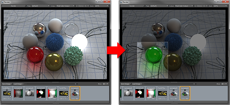
The 3D process is one of constant iteration and refinement. Rendering entire images repeatedly is a significant waste of time and a disruption to the creative workflow. To alleviate some of this pain modo provides the 'Render Region' rendering functionality. Users may use the Left/Right/Top/Bottom functions to specify the region manually, or use the 'Render Region Tool' to specify an area by dragging in any 3D viewport. Additionally, the function can be activated through a button of the 'Render Display' window, under the options tab. When enabled, the next time a render command is invoked (such as by pressing 'F9'), only the area within the region specified will be rendered. The function can be disabled by toggling the 'Render Region' setting.
Render Region: This button toggles the 'Render Region' function on and off.
Left/Right/Top/Bottom: Left/Right and Top/Bottom percentage settings work in conjunction with each other to specify the total rendered region width and height. One could easily render the left half of the image, regardless of the output resolution or aspect ratio, by setting the 'Right' value to 50%. One can also easily set a specific area by click dragging over the rendered image in the Render Preview Window. When you do that, the render region toggle is automatically activated. Outside of disabling the function with the 'Render Region' toggle, a single click anywhere on the 'Render Display' window will restore the render to the full frame.
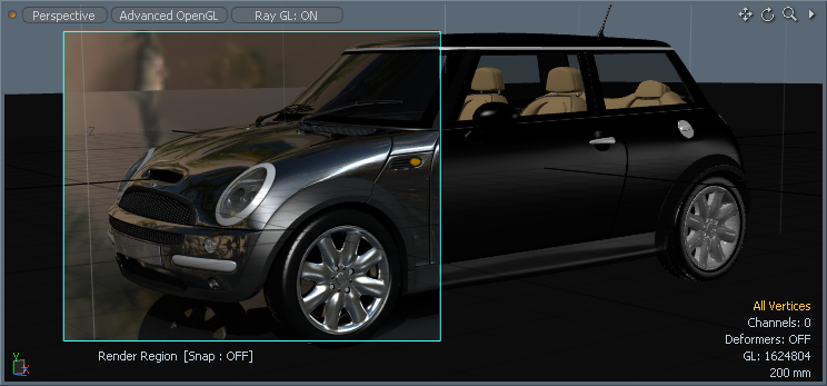
The render region tool provides users a means to easily select a region within a 3D viewport limiting the RayGL rendering to a specific area of the frame. As the RayGL option can be applied to any 3D viewport, the Render Region tool further streamlines the process of iteration and refinement when creating a scene. Users can find and activate the tool in the menu bar under "Render > Render Region Tool". Users need only to select the command, and then LMB+click and drag within a 3D viewport to define the region. One a region has been defined, enabling the RayGL function will limit the subsequent updates to the area inside frame. Users can adjust the quality settings of the RayGL option using the controls found in the Preferences panel. Dropping the tool does not disable the limited region so users may continue to work on a scene while limiting the region of the RayGL rendering. To disable the 'Render Region' option, users can toggle the 'Enable Option' found in the tools properties panel or disable the 'Render Region' option in the Render Items 'Frame' subtab.

TIP: The 'Render Region' function is also very useful when a user wants to render a rather large image for print but is having difficulty doing so. Use 'Render Region' to render smaller sections of the total image and assemble the pieces in an external image editing application.

