
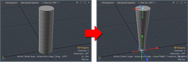
 Found in the 'Deform' subtab of the modeling toolbox, the Taper tool combines the Transform tool with a Linear falloff. At first click the linear falloff is set perpendicularly to the mouse position and automatically scaled to match the currently selected geometry. Dragging the mouse at this time will deform the object with a tapering effect. To precisely place the falloff you can either use the handles to manipulate the falloff after it has been autosized or you can RMB drag away from the handles to reset the falloff and drag it out interactively.
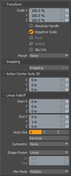
Transform--
Scale: Users may used the X,Y and Z input fields to apply specific scaling values. When adjusting an object interactively in the viewport, the 'Scale' input fields will display the current scale factor applied, providing useful user feedback.
Absolute Handle: The 'Absolute Handle' toggle applies an additional function to the tool handles allowing users to scale the handle itself without affecting the transform amount. In some cases this provides finer control over very large or very small adjustments.
Negative Scale: The 'Negative Scale' toggle enables/disables MODO's ability to interactively apply negative scale values when manipulating the tool handles in the viewport. When disabled, users can always input negative values in any of the input fields directly.
Pivot: Disabled for the 'Taper' tool.
Gimbal: Disabled for the 'Taper' tool.
Child Compensate: (Only in Items Mode) The 'Child Compensate' toggle when disabled will pass along the transform value to any child items of the current selection, when enabled, the child items will ignore any transform values.
Slip UVs: (Only in Component Modes) UV values are generally fixed to specific vertices, subsequently further edits to the geometry may warp, deform or otherwise distort the UV values in undesirable ways requiring users to adjust the map or redo it altogether. To avoid this undesirable result, users can enable the 'Slip UVs' function so as to not disturb any existing UV mapping applied to the geometry.
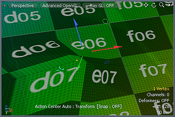 'Slip UVs' function disabled, note texture warping. | 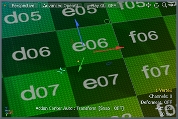 'Slip UVs' function enabled, texture remains even. |
Morph: (Only in Component Modes) The Morph option determines how MODO treats stored Morph information when applying transforms to geometry (Move, Rotate, Scale, etc.). In previous versions of MODO, in order to transform a Morph along with its base, it needed to be selected in the Vertex Map list. If it wasn't, relative Morph map data when recalled would produce distorted, undesirable results. If users were unaware of the requirements, it was easy to accidentally mess up a model. To remedy this problem, there are now three options controlling how the Morph Map vertex data is dealt with when applying any transforms--
None- Unselected Morph data is not affected, though selected (visible) Morphs can still be transformed independent of their source.
Transform- With this option selected, Morph data is transformed along with base mesh.
Keep Positions- With this option Selected, Morph data is converted into a Absolute Morph Map and all vertices retain their pre-transformed positions.
Snapping--
Please reference the 'Snapping' Section of the documentation.
Linear Falloff--
Start X/Y/Z: Defines the starting position of the Falloff as a specific XYZ coordinate value. This end of the line and everything beyond it receives the maximum amount of influence attenuating toward the 'End' position.
End X/Y/Z: Defines the end position of the Falloff as a specific XYZ coordinate value. This end of the line and everything beyond it receives no influence attenuating toward the 'Start' position.
Auto Size X/Y/Z: Users can select either of these three options to automatically scale the 'Start' and 'End' points of the Falloff to match the bounding box size of the selected elements along one of the three axes.
Reverse: Users can select this option to invert the 'Start' and 'End' points reversing the influence of the Falloff.
Symmetric: Users can choose from several options to automatically mirror the influence area of the Falloff-
None- Symmetric function is disabled
Start- Influence of Falloff is symmetrically mirrored across the 'Start' position.
End- Influence of Falloff is symmetrically mirrored across the 'End' position.
Shape Preset: The strength of the Falloff's influence can be controlled along the extent using a 'Shape Preset'-
Linear- Attenuation of Falloff occurs evenly across its range.
Ease-In- Strength of Falloff is greater toward the 'Start' position.
Ease-Out- Strength of Falloff is greater toward the 'End' position.
Smooth- Strength of Falloff is greater toward the center of the Falloff.
Custom- Users can use the 'In'/'Out' options to fine tune strength of Falloff.
In/Out: The 'In' value determines the strength of the Falloff nearer to the 'Start' position, where the 'Out' value determines the strength on nearer the 'End' side of the Falloff.
Mix Mode: In instances where there are multiple falloffs applied to a transform (using the 'Add' option of the Falloff menu), the mix mode defines how each Falloff interacts with the other.

