
The Transform tool combines Move, Rotate and Scale transformations into a single tool. By using the various handles the user can quickly Position, Rotate and Scale from one convenient tool. Holding the 'Ctrl' key will constrain the position transform to a single axis when hauling, and the rotation transform to 15° increments. After applying a transform amount, users may press the MMB to re-apply the previous offset amount, making it easy to apply an edit multiple times. The command can be activated in the 'Basic' subtab of the Modeling viewports, or by pressing the 'Y' keyboard shortcut.
In the component modes, 'Vertices', 'Edges', and 'Polygons', the tool affects the selected geometry directly; when nothing is selected, it affects all active foreground geometry. Active foreground items are those that are visible and selected (highlighted) in the 'Item List'. In 'Items' mode the tool affects all the currently selected items in the Item List, if nothing is selected, then the tools will appear to do nothing. In material mode, it works the same way as in any of the component modes. Lastly, in the 'Center and 'Pivot' modes it modifies the Center or Pivots respectively. Note that users will need to physically select either the Center or the Pivot itself, depending on the mode, prior to activating the tool, as in Items mode, with no selection the tool will appear to do nothing.
When users define any of the various Falloffs MODO provides, application of the tool can be attenuated across a user defined area. For more on using Falloffs, please reference the Selection Falloffs page of the documentation.
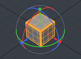
Once the tool becomes active, MODO draws the relevant tool handles within the viewport- arrows for moving, boxes for scaling and circles for rotating. At this point, users may simply click and haul anywhere inside the desired viewport to interactively transform the geometry. Additionally, users may prefer to utilize the various tool handles, constraining the application of the function to one or two axes. The various tool handles are color coded to match the coloring of the different axes, red for X, green for Y and blue for Z. Hover the mouse over a specific handle until it changes to a yellow color and then LMB-click and drag to modify. To interactively scale the size of the handles themselves, users may use the ' - ' and ' = ' keys on the keyboard to adjust them; minus makes them smaller, while equals makes them larger.
The Transform tool also respect the settings for 'Action Center', and will originate the appropriate action from the defined position. For more information on understanding and using Actions Centers, please reference the Action Center page of the documentation
 Transform--
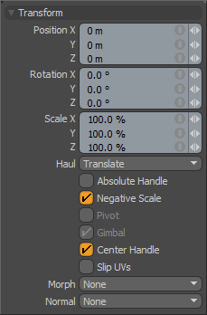
Position: Users may use the X,Y and Z input fields to apply specific offset distance values (calculated from position the object was in when the tool was activated). When adjusting an object interactively in the viewport, the 'Position' input fields will display the current offset distance applied, providing useful user feedback.
Rotation: Users may use the X,Y and Z input fields to apply specific rotation values. When adjusting an object interactively in the viewport, the 'Rotation' input fields will display the current offset distance applied, providing useful user feedback.
Scale: Users may used the X,Y and Z input fields to apply specific scaling values. When adjusting an object interactively in the viewport, the 'Scale' input fields will display the current scale factor applied, providing useful user feedback.
Haul: Users have three options available when hauling in the viewport (i.e. dragging the mouse when not using the tool handles), 'Translate' will allow the users to move the selection, 'Rotate' allows the user to rotate, and 'Scale' would scale the selection.
Absolute Handle: The 'Absolute Handle' toggle applies an additional function to the tool handles allowing users to scale the handle itself without affecting the transform amount. In some cases this provides finer control over very large or very small adjustments.
Negative Scale: The 'Negative Scale' toggle enables/disables MODO's ability to interactively apply negative scale values when manipulating the tool handles in the viewport. When disabled, users can always input negative values in any of the input fields directly.
Pivot: (Only in Items Mode) The 'Pivot' toggle allows users to easily modify an items pivot position without the need to go into Pivots mode. The 'Gimbal' option must be disabled in order to adjust the 'Pivot' option.
Gimbal: With the 'Gimbal' toggle enabled, users can assign rotation values numerically, but may arrive at a situation that produces gimbal lock, the loss of one rotation axis when another's value is too close. Users can avoid this by disabling this setting, but are then unable to apply specific values within the input fields.
Center Handle: The 'Center Handle' option toggles the visibility of the small cube icon at the center of the transform handles in the viewport. When enabled, users can LMB+click and drag on the handle to move the selection relative to the Work Plane. When disabled the handle will not be visible.
Slip UVs: (Only in Component Modes) UV values are generally fixed to specific vertices, subsequently further edits to the geometry may warp, deform or otherwise distort the UV values in undesirable ways requiring users to adjust the map or redo it altogether. To avoid this undesirable result, users can enable the 'Slip UVs' function so as to not disturb any existing UV mapping applied to the geometry.
 'Slip UVs' function disabled, note texture warping. |  'Slip UVs' function enabled, texture remains even. |
Morph: (Only in Component Modes) The Morph option determines how MODO treats stored Morph information when applying transforms to geometry (Move, Rotate, Scale, etc.). In previous versions of MODO, in order to transform a Morph along with its base, it needed to be selected in the Vertex Map list. If it wasn't, relative Morph map data when recalled would produce distorted, undesirable results. If users were unaware of the requirements, it was easy to accidentally mess up a model. To remedy this problem, there are now three options controlling how the Morph Map vertex data is dealt with when applying any transforms--
None- Unselected Morph data is not affected, though selected (visible) Morphs can still be transformed independent of their source.
Transform- With this option selected, Morph data is transformed along with base mesh.
Keep Positions- With this option Selected, Morph data is converted into a Absolute Morph Map and all vertices retain their pre-transformed positions.
Normal: (Only in Component Modes) When working with Vertex Normal Maps, the 'Normal' options control how the map values are affected (see Transform Normals Tool)--
None- Vertex Normal Map values won't be affected at all by the Transform operations.
Edit- Only Vertex Normal Map values will be modified by the tool and only in the selected Vertex Map.
Update- All Vertex Normal Map values, selected or otherwise, and any selected geometry will be modified by the Transform operation.
Child Compensate: (Only in Items Mode) The 'Child Compensate' toggle when disabled will pass along the transform value to any child items of the current selection, when enabled, the child items will ignore any transform values. This is useful to transform a single item in a hierarchy, such as adjusting a joint, allowing it to be repositioned relative to other elements without moving child items.

