
What are Dynamics?
MODO dynamics provide users a way to automatically animate and position elements in a scene. Dynamics allow items to be assigned with real-world physical attributes, such as weight, bounce and friction. Then, through a process called 'simulation', the assigned attributes are evaluated scene-wide, including the further effect of forces over the elements and their interactions with other dynamic elements (collisions). The resulting motion calculations are then cached and saved with the scene for timeline playback and rendering purposes. Dynamically simulating motion in this way produces highly realistic results that would be very difficult, if not impossible, to generate otherwise.
The MODO dynamics system uses the same global evaluation engine as it does for Particles, therefore a lot of the same workflows can be applied to both setups. Due to their deep integration inside MODO, they can also work together, with dynamic items affecting particles and particles affecting dynamic items. This overview page is focused on Dynamics specifically, for more information on working with Particles, please reference the Particles Overview page of the documentation.
Dynamics Workflow Overview
Dynamics first requires a selected element to apply the settings to. While dynamics can be applied to any Locator type item, including Cameras and Lights, to the simulation engine these non-mesh items have no volume to calculate collisions. Therefore any simulation should start with a 'Mesh' item. Another important consideration is the location of the 'Center' position relative to the geometry. The center location defines the rotation origin as well as the center of gravity for the object.
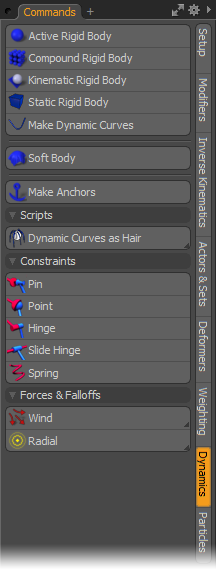
With the target Mesh selected, the dynamic properties are then assigned. This is done using the 'Dynamics' controls toolbox found in the 'Setup' interface. Access to many of the same commands are also available in the 'Dynamics' menu of the menu bar. As with all animated elements, users should be working in 'Items' selection mode when assigning and working with dynamic elements.
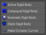
The basic workflow to designate an object as dynamic is to select the target element, assign what type of dynamic item it will be. This is done by pressing the appropriate button in the toolbox, such as 'Active Rigid Body' (toolbox illustrated above). This assigns the item as dynamic and adds a new Property subtab called 'Dynamics' to the 'Properties' panel. Selecting this subtab gives users access to all the various dynamics settings where they can be adjusted. It also adds a new item to the scene, the 'Solver' item that defines the global dynamics settings, such as gravity, and stores the cached evaluations of the computed simulation.
 Dynamic Item Types
The Dynamics toolbox provides users a variety of options for assigning items as dynamic. When any item is tagged as dynamic, controls are added to the items 'Properties' panel under the 'Dynamics' subtab. The attributes for each different option are actually the same controls, but with different base setting specific to the type of dynamic item chosen. All the various controls are covered in the 'Dynamic Item' specific page of the documentation.
An 'Active Rigid Body' is an inflexible, dynamic object that does not deform in any way, reacting to all manner of collisions, constraints, forces, and falloffs, as well as influencing other dynamic items through direct interaction. This setting is great for simulating all kinds of hard objects like blocks, rocks, bowling pins, broken glass, ski poles; really anything that is solid and has weight to it is a good candidate for the Active Rigid Body settings. Active Rigid Bodies are entirely under the control of the evaluation engine during the course of the simulation and will not respond to keyframed animation. Additional control over Active Rigid Bodies is achieved using 'Forces' and 'Constraints'.
For best results, each individual object will need to be its own item layer. Multiple objects within one layer will be treated as a single object, but depending on the shape they may produce unsatisfactory results. For Mesh items, the 'Center' location relative to the geometry defines the rotation origin and also acts as the center of gravity for the weight calculations, so it is best to make sure it is located within the volume of the object. Any Locator type item can be tagged as 'Dynamic', but for any non-mesh items, such as Cameras, and Lights that have no volume to collide with, they will need to be connected to a Constraint of some type in order to keep from flying away.
Compound Rigid Bodies lets users attach a collection of separate (but touching!) Items together, treating them as a single Active Rigid Body. This is done by selecting all the various items and pressing the 'Compound Rigid Body' button. Once designated users can assign a 'Compound Glue' value that will hold the items together during a collision. If the Glue value is exceeded by an outside force during the simulation, this will cause the affected parts of the compound to break off individually.
When assigning the 'Compound Rigid Body' option the dynamics package is added to only a single mesh (the lowest item in the Items List). The other associated meshes will all derive their Dynamics settings from the parent item with the 'Mass' value being equally distributed between all associated layers. Setting a negative 'Compound Glue' value will cause the simulation to treat each Item as a separate Dynamic Body without having to make each one dynamic. The same requirements for 'active Rigid Bodies' apply to the individual items of the Compound body.
The ' Kinematic Rigid Body' option is applied to animated collision objects; specifically to animated 'Mesh' items used for collision. Other Locator type items cannot be used for collision shapes, such as Cameras and Lights. Kinematic Rigid Bodies share the same properties as Static Rigid Bodies, meaning they won't be affected by forces, falloffs or collisions from other objects, but they will play any keyframed transform animations assigned to the item (not Deformations). This is useful for objects that need to interact with other Dynamic items in a controlled way, such as a continuously spinning cage in a lottery ball animation.
Static Rigid Body
A Static Rigid Body is strictly a non moving collision shape. It will not respond to keyframed animation, constraints, forces or falloffs. If the item is animated, the animations will be ignored during the simulation, with the object stopping/resting at the first frame where it becomes a participant in the dynamic simulation.
Dynamic Curve
Dynamic Curves allow users to animate Curve-specific elements, having them react to gravity, collisions, Pins, Anchors and Falloffs. Dynamics for curves can be assigned to both Spline type curves and the two-point polyline chains used for hair guides; curves can be open or closed. The dynamics of the curve are based off of collisions of the vertices that define the curve itself, acting as if they have zero volume. Curves can be made to have volume and width with the combination of the 'Render Curves' option of the Mesh Item properties, and the 'Use Render Radius' option under the Dynamic Items properties (on by default). Then users can specify a 'Curve Radius' value to define the actual size for the simulated curve(s).
Dynamic Curves differ from other dynamic items in that multiple, separate curve elements can all be contained within a single Mesh Item layer, but each will react individually (of course there are settings to change this default behavior), and the 'Center' position for the Items layer relative to the Curves within the layer is irrelevant, having no effect on how the curves deform. Also, the 'Collision' settings have no effect on Curve elements as the collision shape is created automatically. Curves with volume are simulated by creating a virtual collision shape, a capsule, between each vertex of the curve. Note that any polygonal mesh elements within the same layer as the curves will be ignored during the simulation.
The 'Soft Body' designation is a good way to animate flexible items, such as curtains, flags, table cloths, or rubber tires. For the best results, Soft Bodies will need some type of collision element or Anchor in order to keep them from flying away (unless that is the intent!). The collision object could be a bar holding up a banner, or a table setting under a tablecloth. These collision items should be designated as any one of the Rigid Body dynamic types. Alternately 'Anchors', like their real world counterpart, attach Soft Body elements to specific points on the a Rigid Body mesh, fixing them in place. Forces can also be used to interact with Soft Bodies, so Wind can be assigned as well as Turbulence to add some additional realism to the Soft Body results.
Soft Body elements can be open or enclosed Mesh items, and do not require a specific 'Center' position. The shape of the resulting Soft Body is calculated by adding tiny virtual springs between vertices of the mesh. There are different settings for each type of spring; for 'Stiffness', 'Struct' (Structure) and 'Sheer'.
Since only the vertices of the Soft Body are calculated for collision, there may be cases where sharp or pointed areas of the colliding mesh show through, this can be remedied by increasing the 'Margin' value under 'Collision' for the target object.
Anchors
The 'Make Anchors' options is used to connect Soft Body items to Rigid Body items. For best results, the 'Rigid Body' item should be a Passive Rigid Body, to keep it from flying away. The 'Anchor' option could be useful to connect a flag to a flagpole. In order for the Anchor option to work, users must follow this specific workflow- First in 'Items' mode, users need to select the target Soft Body item AND the target Passive Rigid Body item. With the items selected, change into the 'Vertices' mode (press '1' on the keyboard) and select at least one vertex on the Soft Body item, and at least one more on the Rigid Body (selection order isn't important). With the vertices selected, press the 'Make Anchors' option in the Dynamics toolbox. The two items are now rigidly connected together via an additional 'Anchor' item added to the 'Soft Body'. To break the connection, simply delete the resulting 'Anchor' item. To make adjustments, remove the Anchor and recreate it, following the above instructions.
Collision Detection
Collision in Dynamics is the calculations that restrict intersections between surfaces. It is, for example, what allows a ball to bounce and roll down a stair case. Without it the dynamic bodies would simply pass through one another with no regard or knowledge of the opposing item. In the 'Dynamic' subtab in the Item's 'Properties' panel are the settings that control the object and how it acts. The most important setting in this tab is in regards to Collision as it defines how the Dynamics computations see the object.
By default MODO assigns a collision type based on a best guess from the actual geometry in the item layer. For a flat polygon this would be 'Plane' or for a round object, like a ball, this would be 'Sphere'. However, sometimes MODO guesses wrong. The wrong collision shape can cause intersection errors and produce unsatisfactory results, so it's a good idea to check that the best collision shape is being assigned. In most cases the best results are obtained using the simplest collision shape appropriate to the geometry. Collisions relating to Soft Bodies are only required when there are issues with the surface intersecting itself, which can be fixed by enabling the 'Self Collision' option.

TIP: To increase evaluation performance of rigid bodies, low resolution collision geometry can be created separate from the high resolution mesh to simplify calculations during the simulation. Once the dynamics are evaluated and cached, the low resolution collision objects can be set to 'Render - No' and the high resolution object can be parented to the low res collision object for final rendering.
Constraints
If Dynamics were strictly limited to only calculating collisions between objects, it would very quickly become daunting to produce even modestly complex simulations. Depending upon collisions exclusively to generate the mechanics of say a rotating drive shaft for a vehicle would no doubt introduce errors and be quite costly to calculate. Constraints are essentially joints that connect two dynamic bodies together, producing much more accurate results than collision detection alone, with very little calculation overhead. Constraints come in a variety of types that cover most any type of joint users would need. Clever users will also be able to stack more than one constraint to produce an even more complex effect, such as combining a Point Constraint with a Slide Constraint to produce a swinging and sliding motion, much like riding suspended from a zip-line -a ride where the participant slides down a long, taut cable suspended between two posts.
Forces
In the real world, objects are constantly subject to numerous forces that affect their motion in subtle and not-so-subtle ways; wind, gravity, friction among others. Dynamics offers a variety of additional specific 'Forces' all to produce even more realistic physical simulations. Gravity is the chief overall governing force acting on all dynamic bodies globally. Because of this ubiquity it is part of the Dynamics Solver item, affecting all items globally. Its default value is meant to simulate the same downward pull at full size (1:1 scale) as gravity in the real world. If a simulation isn't reacting as one might expect, it's a good bet that the scene isn't modeled to real world size, as very large items will react much differently under the same circumstances than very small items. Users can of course scale their objects, or scale the simulation to match more closely the expected result.
MODO also offers seven additional force types allowing users further control of the simulation. Linear, Drag, Radial, Turbulence, Vortex, Wind and a Curve Force. These are added as Locator type item layers in the 'Items' list and, by default, affect dynamic items globally, just as the Gravity value does, although this can be modified using the Schematic view. Each 'Force' has its own particular function which is covered fully on the Forces page of the documentation.
Falloffs
Falloffs can be incredibly useful to provide additional control over Forces. For instance if Wind was affecting flower petals drifting lightly on the breeze, and the Soft Body petal items then land inside of a box. To keep the ones inside the box from being affected by the wind a 'Falloff' would be used to eliminate the wind from inside the box, increasing the realism of the simulation.
Dynamics uses the same Falloffs used for other deformers in MODO. Deformation Falloffs are meant to modulate (reduce or increase) the effects of forces on dynamic items within the area of influence of the Falloff itself. Not to be confused with MODO modeling falloffs; used for geometry creation and layout. Conceptually they are very similar, but instead of being applied as a function, Dynamics falloffs are added as a Locator type item to the 'Items' list where users can select them and modify their attributes and even animate them within the scene. In the items properties, users can define an attenuation range that modulates the force it is applied to.
Unlike Forces that affect items globally, Falloffs must first be attached to the Force item it is attenuating in order to produce a result. This can be done several ways. Generally, it is applied by selecting the target 'Force' item(s) prior to adding the Falloff, when using the 'Add Falloff' button in the Dynamics toolbox. When applied to a Soft Body item, users can use the 'Deformers' viewport, and select the 'Soft Body' Influence from the list; by RMB+clicking on the item to open the context menu, users can select the 'Add Override' option and select one of the Falloffs, automatically assigning it to the Soft Body. Additionally, users can use the 'Schematic' viewport to connect the two; dragging both items into the viewport (via drag and drop) and connecting the output of the Falloff item to the input of the Force item. For more information on using the Schematic Editor, please reference that page of the documentation.
Dynamic Replicators bring the worlds of Dynamics, Particles and Replicators together, allowing users to assign Mesh items to a Particle Simulation to spray blasts of dynamic, colliding objects. There are two basic types of Dynamic Replicators- 'Kinematic' which act only as animated collision objects (acting like replicated 'Kinematic Rigid Bodies'), but have no internal collision calculated between replicas, and 'Dynamic' which will act as normal 'Active Rigid Bodies'; generated automatically by the Particle Simulation.
Kinematic
Replicators combined with a Particle Simulation can be used strictly for collision shapes, this can be useful in cases where it is desirable for the replicated items to affect other non-replicator 'Dynamic Rigid Body' elements, but not be affected by inter-object collisions between replicas. The individual replicas would essentially be 'Kinematic Rigid Bodies' in how they react to other elements. They wouldn't be affected by Forces, Falloffs or other dynamics objects; they would simply have affect over regular Active Rigid Bodies, same as a 'Force' would, causing them to react to the collisions.
Creating Kinematic Replicators is done by first creating a Particle Simulation of some sort. This can be using any of the various emitter types available. Next a Replicator will need to be created, this can be added in the Items list using the 'Add Items' function under the "Particles > Replicator" menu. Once added, the Particle Simulation should be designated as the 'Particle Source' in the 'Replicator' Items Properties panel, and the target 'Mesh Item' (or a 'Group' of Items, for variations) designated as the 'Prototype' option. Once defined, the Replicator item itself will need to be selected in the 'Items List' and then in the 'Dynamics' toolbox, tagged as a 'Kinematic Rigid Body' by LMB+clicking the toolbox button of the same name. This adds a subtab to the Properties panel of the Replicator item titled 'Dynamic Replicator', where the various dynamic attributes can be adjusted, if necessary, such as the 'Collision Shape' for the prototypes and their 'Bounce' and 'Friction' values.
Dynamic
Replicators can also be combined with a Particle Simulation to generate fully dynamic Mesh items that collide and react to Forces and Falloffs. Any type of 'Particle Emitter' can be designated as the 'Particle Source' for a 'Replicator'. Adding in 'Dynamics' allows the Replicas to act as individual active rigid body elements, created dynamically by the settings of the Particle Simulation.
To create a Dynamic Replicator, users will, of course, need a Particle Simulation, and a Replicator with the target Mesh specified as the 'Prototype' and the Particle Simulation specified as the 'Point Source'. The same workflow as for the Kinematic Replicators above. Once properly assigned, making the Replicator dynamic is done by selecting it in the 'Items List' and tagging it as a 'Active Rigid Body' by LMB+clicking the 'Dynamics' toolbox button of the same name. This action adds a 'Dynamic Replicator' item to the scene. This new item contains the Dynamic attribute settings for the Dynamic Replicas, such as settings for the 'Collision Shape', 'Bounce', 'Friction' and 'Density'. Selecting the item in the 'Items List' will display the attribute settings in the 'Properties' Panel.
TIP: One consideration to keep in mind when making Dynamic Replicators is that the replicated items should be generated from an emitter that is sized large enough to accommodate the volume of replicated mesh items without grossly intersecting, while also taking in to consideration the 'Emission Rate' and Emission Speed' values. Additionally the 'Dynamic Replicator' item has an option 'Time Until Collision' that delays the enforcement of collision detection on emitted Replicators that can also be used to eliminate any collision errors that may occur.
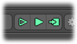
There are three buttons used when simulating both dynamics and particles, each with a unique purpose. The two left buttons provide continuous real-time simulation directly in the 3D viewports, allowing users to adjust settings and move objects and see the results as the settings are changed. The 'Preview at Current Time' button (hollow arrow) specifically plays the simulation at the current timeline position ignoring keyframed animation, the 'Preview Animation' button (solid arrow) cycles through playing the timeline with all keyframed animations. When either button is pressed, the buttons themselves will change to 'Stop' buttons which can then be pressed to stop the simulation playback.
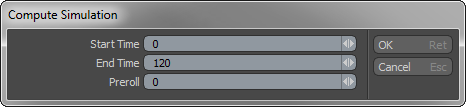
The last button is the 'Cache Simulation' button. Pressing this one opens the evaluation dialog box where users enter the desired frame range and designate a 'Preroll' value, a designated number of frames prior to the first frame where the simulation will actually begin calculating. Useful for instance when there needs to be a flow of particles at the 'Start Time'. The main differences between the real-time playback controls and computing the simulation is that the 'Compute Simulation' option fully calculates all Physics Rate (subframe) step values, especially important for collisions to properly evaluate intersections. The real-time controls always use a frame step of 1, which may not provide enough accuracy for fast or complex dynamic simulations.
Additional Dynamics Considerations
Items vs. Components
Animation in MODO applies only to 'Items'. Keyframes are always set while in 'Items' mode with the modeling of objects done while at the component level, in the 'Vertices', 'Edges' and 'Polygons' modes. It is helpful for users to have an understanding of the differences between these modes. Layers in the items list should be thought of as containers. In 'Items' mode, users are editing the entire container, but while in the component modes, users are editing the contents of the container. Dynamics acts only at the item level, where each layer in the 'Items' list is its own individual dynamic object. Therefore, if users wish to break apart a wall, each brick will need to be its own individual item layer. Users can easily accomplish stacks of bricks by simply creating the first brick item, and then assigning the 'Active Dynamic Body' tag to make the brick dynamic. Next, applying the 'Array' function in items mode will stack subsequent bricks, each inheriting the dynamics of the master object. With the wall created, all it takes is an animated wrecking ball to topple the bricks to the ground, tagged as a Kinematic Rigid Body, of course.
The weight of Rigid Body objects is dependent on the position of the item's 'Center'. The center point for an object doesn't only represent the center of rotation for the object, when using Dynamics it also represents the center of mass for the object. Dynamics will assume the weight of an object is equally distributed around the center point, so objects will move based on this assumption. If the center point is placed too far away from the item's actual center, or worse outside the volume of the object, odd behavior is sure to occur. Users can see an object's 'Center' position by hovering over the 3D viewport in question and pressing the 'O' key. In the 'Visibility' subtab, there is an option to show Centers for selected items.
There are several ways to deal with a center that's been moved, the easiest is to select the item in 'Items' mode and invoke the menu bar command "Edit > Center to Bounding Box > Center"; this will automatically move the Center point to the objects actual bounding box center (a bounding box is based on a model's overall extents).
Users cannot manually (by keyframes) animate active rigid bodies, however, sleeping objects can be animated (and are handed off to Dynamics once they are awakened, a mode where dynamic items can be triggered by a specific event). If the animated object requires rotations from a position other than the object's true center, users should modify the 'Pivot' position and animate from there to maintain the proper center of mass.
Accuracy
The number one issue users run into when calculating a simulation is objects passing through one another (like dropping chain links together to form a chain and they fall right through each other). While it can be caused by a multitude of issues, it is most often caused by the speed at which objects move. At one frame they were apart from each other, the next they had passed right through one another. This means the default subframe calculations didn't have ample time to calculate the collisions of the objects. Even though we only see the result at the whole frame values, and lot can happen between frames.
Users can increase this sub-frame accuracy with the 'Physics Rate' values found in the Dynamics solver (properly calculating subframes for all keyframed items as well). Doing so makes Dynamics more accurate, however the additional calculations take longer to compute; more accurate = slower. Users should experiment with different values to find one that produces acceptable results with the least number of steps. Keep in mind that sub-frame steps will only be calculated for cached simulations. The real-time options always only calculate per-frame, so for fast simulations it may be necessary to cache the simulation each time to properly preview accurate results.
Schematic Viewport
Dynamic simulations can be controlled nodally using the Schematic viewport. Actually, in the background a node graph is being created as users add dynamic elements to a scene. It will seem hidden until any of the Dynamic elements are added to the Schematic. As the dynamic elements are added one-by-one you can see that they are already connected. Dynamics take advantage of the special 'Relationship' connectors to define links between items, these connectors look like diamonds instead of circles. They represent bi-directional information flow between elements, unlike regular channel connections that are used to drive a channels information from one item to another. It can be a good idea to familiarize oneself with the Schematic viewport as it allows advanced users the ability to better control and customize the Dynamics simulation, for instance users can connect a 'Force' node to an individual mesh item and it will only affect that single mesh instead of applying itself globally.
TIP: In addition to 'Mesh' items, 'Instances' can also be tagged as the various types of Rigid Bodies- 'Active', 'Kinematics', and 'Static'. While they can be tagged as Dynamic, due to their structure 'Static Mesh' Items will produce no collisions between other dynamic items.
 Bullet Physics
Dynamics is based on Bullet Physics, an open source collision detection and rigid body dynamics library that is free for commercial use, under the ZLib license. Thank you to Erwin Coumans and the Bullet developers for their efforts and generosity.

