
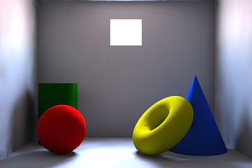
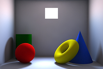
Portals are not lights in the traditional sense, as they produce no illumination by themselves. They are meant more to control lighting, especially that of interior renders that rely mainly on Global Illumination. Think of them as gathering rays and focusing them into a specific area. In this following example, the interior is illuminated solely by the environment, no lights are being used whatsoever. At the default settings, the image on the left exhibits some chattering and splotches, especially in the area of shadow transitions. In the second image on the right, a Portal has been added to the scene and set with 512 light samples. This produces a much smoother result with no other setting or value changes.
|
|
|
The main use for 'Portals' is not surprisingly to be placed at openings; anywhere light would enter into an interior, such as a window, door or skylight. For best results users should position the portal directly outside the portal itself (or inside depending on the shape of the opening) and scale it to be slightly larger than opening. Users can also adjust the shape of the portal to better represent the shape of the window, either as round or rectangular. Users should also note it is better to use fewer Portals than more, as this can add significantly to render calculation times, for example when representing a multi-paned window, using a single Portal scaled to the over-all window size would be better than individual Portals for each pane. Users should also note that Portals take their color from the environment behind them and therefor have no Light Material setting, like those of other direct light sources.
Portal
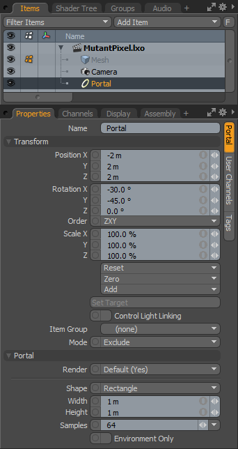 Name: This data field displays the current item name. Users may easily change it by LMB-clicking within the field and typing the new name.
Transform--
Position: An Item transform that allows the user to numerically position the Portal item in XYZ space. By default, Position transforms originates from the items center position.
Rotation: An Item transform that allows the user to numerically set the rotation of the Portal item. By default, Rotation transforms originates from items center position.
Order: Allows the user to set the order that rotations are applied to the Portal item. Changing the order that rotations are applied can sometimes help to reduce or eliminate gimbal lock when animating.
Scale: An Item transform that allows the user to numerically set the scale of the item. By default, Scale transforms originate from the Center position.
Reset: Resets the selected transform values to (0,0,0) returning the items back to the world space center position.
Zero: Returns the Portal items Center position to the world space center (0,0,0) without changing the position of the Portal item itself. This is done by the addition of a negative transform added to the Transform channels.
Add: Transform Items are the channel groups associated to an item that store its transform values, controlling its position, rotation and/or scale. By default, new items do not have any transform items associated with them (even though they are visible here within the Properties panel). This is useful as an optimization as only the necessary transforms are added on an as-needed basis, reducing scene overhead. There are several ways to add them. One is by simply transforming the target item with one of the various transform tools (or by editing the values input fields). This action will cause the particular transform item to be added automatically to the 'Channels' viewport list. The 'Add' function here can also be used to add the selected set of transforms to the Channel list while keeping the default 0,0,0 values (a necessary step for 'Referencing', in order to override the channels, they must first exist).
Set Target: By selecting the Light item, and a single additional item in the item list, and then pressing 'Set Target', this function allows users the ability to target specific items in a scene, automating the rotation of an item, so that it continuously points toward the targeted item. Once activated, additional options appear--
Remove Target: Removes the target link between the two items.
Enable: Toggling this option off temporarily disables the targeting function while retaining the link between the items.
Set Focus Distance: This option sets the focal distance for DOF when targeting camera items to other item.
Roll: Provides the ability to offset the items rotation angle away from the target.
Time Offset: Provides users the ability to time offset, by a number of frames, how the light follows the target item. It can either be delayed behind it with a negative value, or run ahead of it with a positive value.
Control Light Linking: Illumination on a surface is generally controlled by the 'Shader' item in the Shader Tree. Within the Shader it is possible to control a lights affect on a surface with Light Linking. As its name describes, it links the illumination affects of a Group of Lights to specific Items or Material Groups. When the 'Control Light Linking' option is enabled on a Light item, it will act as an individual Light Specific override to the Shader, allowing users to 'Include' or 'Exclude' a specific lights illumination on a group of items.
Item Group: The 'Item Group' option determines the specific Group of item layers in the scene that will be affected by the Light Linking. The Group needs to be defined in the Groups viewport panel. This can be done easily by selecting the target items while in 'Items' mode and then in the Groups palette LMB+click the 'New Group' button. Define a name for the group in the pop-up dialogue and choose the 'From Selected Items' option and click 'OK' to accept. Once the Group is defined, select the named group here.
Mode: The 'Mode' option determines whether the light will be 'Included' meaning it will only affect the Items in the specified Item Group, and 'Excluded' by all other surfaces, meaning it will be ignored by any items in the specified Item Group.
Portal--
Render: This drop down menu allows the user to select from 3 choices, when set to 'Default', the user can enable/disable Portals using the visibility function "![]() " of the item list. When the Portal is visible, it contributes to the final rendered scene and when invisible, it will not. On some instances the user may prefer to fix this state, setting the Portal as 'On' (enabled) or 'Off' (disabled) regardless of visibility. Also useful for workflows that auto toggle visibility, saving the user from manually enabling Portals for test renders.
" of the item list. When the Portal is visible, it contributes to the final rendered scene and when invisible, it will not. On some instances the user may prefer to fix this state, setting the Portal as 'On' (enabled) or 'Off' (disabled) regardless of visibility. Also useful for workflows that auto toggle visibility, saving the user from manually enabling Portals for test renders.
Shape: This option determines the final shape of the Portal, set as either Rectangular or Elliptical. User can then adjust the 'Width' and 'Height' options to further define square, rectangular, circular or oval type shapes.
Width/Height: This value determines the actual size of the Portal. Users should size the Portal to approximate the overall size of the window it is representing.
Samples: This value determines the Portals light gathering ability, having greater numbers of Samples will increase the overall accuracy of the final rendered image, but also keep in mind that additional rays will also adversely affect render times, so users should adjust the rays to find a balance of quality versus render time.

