
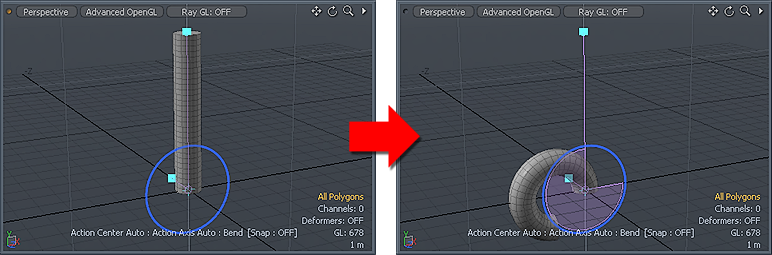
The Bend tool allows users to quickly deform selected geometry in a curved manner. The simplest example would be to take a straight cylinder or tube and flex it into an arc, producing a section of a torus. The Bend tool consists of two main handles; a bend "spine" and the bend angle disc, controlling what gets bent and how much is is deformed respectively.
Usage
To use the 'Bend' tool, locate the tools button in the 'Deform' subtab of the default modeling toolbox and LMB click it. This activates the tool, showing the tools attributes on the 'Tool Properties' panel. Next, in the 3D viewport, LMB+click at the base location where the bend should start from, initiating the interactive editing mode and drawing the tools handles. The center of influence for the Bend tool is placed at the intersection of the initial mouse click and the Work Plane. It may be necessary to position the Work Plane appropriately prior to activating the tool as the Work Plane also determines the initial orientation of the tool.
There are two main handles that are used to bend the target. The circular 'Angle' handle which works like the standard Rotate tools handle controls the amount of bending, and the 'Spine' handle which determines the influence area for the operation. The round Angle handle can be clicked and dragged in a circular direction, the greater the distance from the initial click, the greater the bend amount. Also, by moving the cursor (while click+dragging) further away from the handle will allow finer control of the angle. The spine determines which area of the target is affected. When the tool handle is created on the initial click, its height is determined by the bounding box height of the target geometry. This allows the entire length of the target to deform. Users can click+drag the small blue cube on the top of the handle to change its length, allowing a partial bend deformation. Hovering over it will change its color to yellow indicating a mouse click will move it. Clicking+dragging will adjust the position of the spine on the axes relative to the Work Plane, holding 'Ctrl' while moving will constrain it to a single axis. The following options, found in the Tool Properties panel can be adjusted manually while the tool is active for more precise bending deformation-
 Bend--
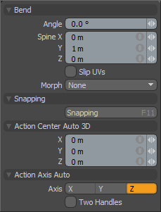
Angle: This value represents the amount of bend that is received by the geometry at the end of the spine. The bend tool automatically fades this amount across the geometry selection down towards the base of the bend tool to accomplish the intended bending effect.
Spine X/Y/Z: This triplet value sets the end of the spine handle. The handle can be adjusted interactively in the 3D viewport by LMB+click and dragging or numerically typing in the position in the numeric entry field.
Slip UVs: UV values are generally fixed to specific vertices, subsequently further edits to the geometry may warp, deform or otherwise distort the UV values in undesirable ways requiring users to adjust the map or redo it altogether. To avoid this undesirable result, users can enable the 'Slip UVs' function so as to not disturb any existing UV mapping applied to the geometry.
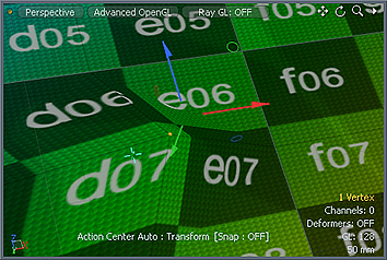 'Slip UVs' function disabled, note texture warping. | 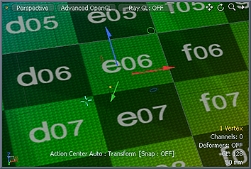 'Slip UVs' function enabled, texture remains even. |
Morph: The Morph option determines how MODO treats stored Morph information when applying transforms to geometry (Move, Rotate, Scale, etc.). In previous versions of MODO, in order to transform a Morph along with its base, it needed to be selected in the Vertex Map list. If it wasn't, relative Morph map data when recalled would produce distorted, undesirable results. If users were unaware of the requirements, it was easy to accidentally mess up a model. To remedy this problem, there are now three options controlling how the Morph Map vertex data is dealt with when applying any transforms--
None- Unselected Morph data is not affected, though selected (visible) Morphs can still be transformed independent of their source.
Transform- With this option selected, Morph data is transformed along with base mesh.
Keep Positions- With this option Selected, Morph data is converted into a Absolute Morph Map and all vertices retain their pre-transformed positions.
Snapping--
Please reference the 'Snapping' Section of the documentation.
Action Auto Axis--
The 'Action Auto Axis' will position the 'Angle' adjustment handle relative to the position of the Work Plane when the tool is first initiated in the 3D viewport. Users can select alternate axes if the initial selection is incorrect for the desired bending direction. For more on Action Centers, please reference the 'Action Center' section of the documentation.
Two Handles: Draws an additonal two handles in the 3D viewport allowing users to interactively adjust the orientation of the handle itself for off-axis bending.

