
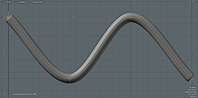
The Bezier Deformer is an excellent way to apply deformations in a continuously smooth manner. This can be extremely useful for long tube-like structures, such as tentacles, tails, whips and a multitude of other applications. The Bezier Effector is functionally identical to the 'Spline Effector', but uses the somewhat easier to manipulate Bezier curve handles where users can control the line interpolation between anchor positions using additional handles, allowing for a more intuitive workflow.
The Bezier Deformer works as a Group of Locators that define a Bezier style curve through their collective locations. Their initial positions (defined as the Setup Position) determine the undeformed state of the target mesh, and as each Locator is moved the difference between the unmodified curve is calculated and applied to the mesh as the deformation (this is why Curve Deformers will always appear to have two actual curves associated with them). As with many functions of MODO, there are several ways to go about assigning and applying a Bezier curve for deformations.
No Initial Curve
It is not a requirement that a user create a Bezier curve prior to applying a Bezier Deformer, as a 'Create Spline' dialogue box opens whenever the Bezier Deformer is applied to a Mesh item layer. Users must keep in mind that the resulting curve generated aligns along one of the three axes in a perfectly straight line, centered on the chosen axis. Users will either need to model the target geometry to match this requirement, or enter Setup Mode after the fact, and reposition the generated curve to coincide with appropriate locations relative to the geometry its meant to deform.
To apply the Deformer itself, users must first select the target Mesh Item layer either in the 'Items' list or the 3D viewport. With the target item selected, users can then either press the interface button 'Bezier' found in the toolbox within the 'Setup' interface layout under the 'Deformers' subtab or they can RMB+click on the target layer in the 'Items' list and select the "Add Deformer > Effectors > Bezier Effector" from the contextual menu. This opens the following dialog-
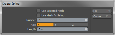
The only values that need to be modified are the 'Number', 'Axis' and 'Length'. Number represents the number of 'Bezier Node' control positions generated along the length of the curve. More control points will provide finer control over the deformation, but also are more difficult to deal with. Since the deformation smoothly attenuates between each location, users should define the bare minimum number of point necessary to obtain the desired effect. The 'Axis' value determines along which axis the resulting spline will be generated, and 'Length' determines overall length of the resulting curve, centered at the world origin. The base of the generated curve will be on the negative side of the specified axis and increment towards the positive direction. Clicking 'OK' or pressing 'Enter' will accept the values entered and generate the 'Bezier Deformer'. This will also add a number of 'Bezier Node' items into the 'Items List', based on the 'Number' value defined. These are the items that will be manipulated in the scene to actually deform the target geometry.
If modifications are necessary, users can press the 'Setup' mode button found in the 'Setup' interface layout,to enter the 'Setup' action state, allowing users to modify the curve relative to the target geometry without generating any deformations (it will also temporarily disable any position changes applied to the curve outside of 'Setup)'. When properly positioned, users can exit the 'Setup' action state and then change the positions of any of the 'Bezier Node' items to actually deform the target mesh. This is done by simply selecting the 'Bezier Node' item itself and moving it with the transform tools, setting keyframes as necessary (if animation is desired). There are also extended control handles on the Bezier node item that can be LMB clicked on to change the incoming and outgoing curve shape more intuitively.
User Created Curve
If it is desired to create a custom Bezier Curve to use as a Deformation controller, users will need to generate this curve in the same Item layer as the target mesh its meant to deform (this can also be done by a cut-and-paste action prior to invoking the add 'Bezier' deformer command). Users can draw the spline with the 'Bezier' tool.
Once the Bezier is created, adding it as a deformer to the mesh requires the user to be in the 'Polygons' component mode with the target Curve selected (and only the target curve). With the target Bezier curve selected, users can then either press the interface button 'Bezier' found in the toolbox within the 'Setup' interface layout under the 'Deformers' subtab or they can RMB+click on the target layer in the 'Items' list and select the "Add Deformer > Effectors > Bezier Effector" from the contextual menu. This opens the following dialog-

The only value that will need to be modified in the case of the user created curve is to enable the "Use Selected Mesh" option, instructing the tool to use the previously selected curve. The rest of the options are unnecessary, as everything else will key off the curve itself. Clicking 'OK' or pressing 'Enter' will accept the values and generate the 'Spline Deformer'. This will also add a number of 'Bezier Node' items into the 'Items List', based on the number of vertices in the specified Bezier curve. The 'Bezier Node' items are used to actually deform the target mesh. This is done by simply selecting the 'Bezier Node' item itself and moving it with the transform tools, setting keyframes as necessary (if animation is desired). There are also extended control handles on the Bezier node item that can be LMB clicked on to change the incoming and outgoing curve shape more intuitively.
Spline Effector--
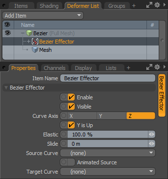
To access the options related to the Bezier Effector, users can select the Bezier Effector item itself within the 'Groups' viewport as the parent of the Locators, or in the 'Deformers' palette and view the associated attributes in the 'Properties' panel.
 Enable: Toggles the effect of the layer on or off. When unchecked (disabled), the layer has no influence on the scene. However, disabled layers are still saved with the scene and its values are persistent across MODO sessions.
Visible: Toggles the visibility of the curve representations in the 3D viewport.
Curve Axis: The 'Curve Axis' setting is critical for twisting and scaling as it decides how the Locator transform channels are used, so rotations along the axis add twist, the other rotation axes are ignored. Scaling perpendicular to the axis stretches the mesh perpendicular to the Curve Axis.
Y is Up: The 'Y is Up' toggle is used with the 'Curve Axis' option to set where the twist coordinates' zero-twist value is. Disabling this option may be helpful to avoid kinking in a deformed mesh when twisting (in certain cases).
Elastic: The 'Elastic' option determines to what degree the deformed item is stretched along the curve to match its overall length. A setting of 100% (default) stretches the deformed area to the same lengths as the target curve, this deformation attenuates toward 0% where the item will retain its original undeformed length along the curve. Deforming always originates from the start of the curve itself. For items that are shorter than the target deformation curve, apply the 'Slide' option to position the geometry along the curve.
 Elastic Value 100% | 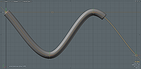 Elastic Value 50% | 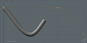 Elastic Value 0% |
Slide: The 'Slide' option is meant to move the target along the length of the curve, especially when the target item is shorter than the deforming curve. One example of how this could be useful is to animate a snake along a predetermined path, by setting the 'Elastic' value to 0% and then using the 'Slide' option to deform the snake along the curve.
Slide Value 0m | 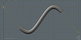 Slide Value 1m | 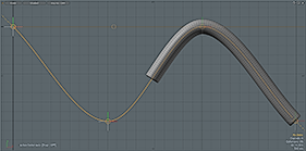 Slide Value 2m |
Source/Target Curve: The Source and Target Curve options allow an additional way for users to deform a target mesh using a custom created curve that is itself deformed by another Deformer (bypassing the need to create any handles to manipulate the curve). You'll first want to create the curve and then duplicate the curve to a new item (so there are two identical versions as separate item layers). Only the single curve should be in each item layer. Next, assign the deformation to the curve that will represent the 'Target Curve' (for example creating a Morph for the curve). Next, by adding a Spline Curve Deformer to an Item (see above) and not specifying a specific curve, just the Effector will be created. Users can then specify the deforming curve as the 'Target' and the undeformed version as the 'Source'.
Animated Source: This option toggle should be enabled when the Source Curve is animated, meaning it will be constantly evaluated, otherwise when disabled, its position will only be evaluated on the first frame.

TIP: When you find a curve is reversed from what is desired, the point order can be inverted simply by selecting the target curve in one of the component modes and pressing 'F', now what was the start will be the end and vice-versa (This is the same command and action as flipping a polygons face normal).
 Bezier Node Item
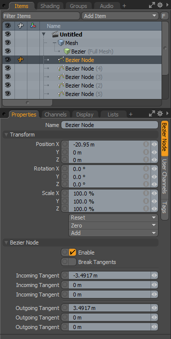
The 'Bezier Node' is the actual item that is manipulated in the scene to control the deformation of the target geometry. Multiples of them will define a virtual Bezier curve that deformers the target mesh. The Bezier Node has settings for its 'Position' as well as the position of the control handles.
The 'Scale' and 'Rotation' values will modify the manipulator handles, but provide no influence over the actual deformations of the target, that is controlled strictly by the position of the Incoming and Outgoing Tangent control settings. These values can be set manually in the Items Properties panel when it is selected, or they can be LMB+clicked in the viewport and transformed directly. Moving the handles always moves two axes at once, and they always move relative to the current Work Plane position.
Name: This data field displays the current item name. Users may easily change it by LMB-clicking within the field and typing the new name.
Transform--
Position X/Y/Z: These Position values define the location in 3D space for the Bezier Node, their position relative to the others defines the curve that is used to deform the target mesh.
Rotation X/Y/Z: These Rotation values do not produce any influence over the deformations of the target mesh, please adjust the Tangent Handles instead to twist the incoming or outgoing angles of the Bezier curve.
Scale X/Y/Z: These Scale values do not produce any influence over the deformations of the target mesh.
Reset: Resets the selected transform values to (0,0,0) returning the items back to the world origin, although as a deformer this will change the location of the Bezier Node influencing the deformation of the target mesh, unless applied in the 'Setup' action state.
Zero: Resets the chosen transform property values to '0', leaving the 'Center' position and Mesh position intact. This is done by adding a negative transform item to the Mesh items Channels.
Add: Transform Items are the channel groups associated to an item that store its transform values, controlling its position, rotation and/or scale. By default, new items do not have any transform items associated with them (even though they are visible here within the Properties panel). This is useful as an optimization as only the necessary transforms are added on an as-needed basis, reducing scene overhead. There are several ways to add them. One is by simply transforming the target item with one of the various transform tools (or by editing the values input fields). This action will cause the particular transform item to be added automatically to the 'Channels' viewport list. The 'Add' function here can also be used to add the selected set of transforms to the Channel list while keeping the default 0,0,0 values (a necessary step for 'Referencing', in order to override the channels, they must first exist).
Bezier Node--
Enable: Toggles the current Bezier handle on and off for the deformation. When enabled, it will influence the deformation of the target mesh. When disabled, its influence will be ignored.
Break Tangents: For Bezier control handles, they are by default tangent (straight or linear) on opposing sides of the node position, producing a smooth curve across the Bezier nodes position. Enabling the 'Break Tangents' control will allow the handles to be independent of each other, creating a corner or sharply angled curve joint.
Incoming Tangents: These three values represent the X,Y and Z position values of the Incoming Tangent handle relative to the actual position of the Bezier Node. Users can manually enter a location here to manipulate the curve shape, or LMB+click on handles in the 3D viewport and adjust two axes simultaneously, relative to the position of the Work Plane.
Outgoing Tangents: These three values represent the X,Y and Z position values of the Outgoing Tangent handle relative to the actual position of the Bezier Node. Users can manually enter a location here to manipulate the curve shape, or LMB+click on handles in the 3D viewport and adjust two axes simultaneously, relative to the position of the Work Plane.

