
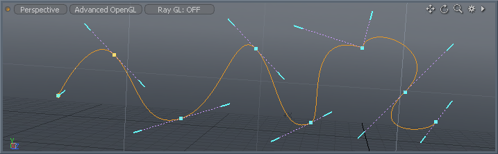
A Bezier Curve is a type of curve defined by additional off-curve control handles. Bezier Curves were originally developed for computer modeling in automotive design, but are popular in many vector drawing applications, providing a more familiar means of generating curves as they allow the user to interactively control the amount of incoming and outgoing curvature for each control point.
Usage
The Bezier tool is found in the 'Basic' subtab of the modeling toolbox, one may have to RMB+click to open the button popup menu to find it (by default it is located under the 'Pen' tool button). Alternatively, users can also access it by opening the 'Curve' palette, found in the menu bar under "Geometry > Curve Palette". LMB+click the button to activate the tool. Next, in the 3D viewport, click to position the first control point and then continue to drag the mouse cursor to create the bezier handle. Releasing the mouse button will set the handle length. Subsequent clicking and dragging will draw additional control points and handles with a curve segment drawn between each vertex. Control points will always be created at the intersection of the Work Plane and the mouse button click. The curvature of the segments between control points is defined by the bezier handles (called 'endpoint tangent vectors'). While the tool is active, users can hover over any of the control points (changing them from blue to yellow) and LMB click and drag to reposition it. Points will always move on the two axes relative to the current Work Plane, so rotating the viewport to change an axis may be necessary. Handles are edited in the same manner. Pressing and holding the 'Ctrl' key when editing handles will break tangency allowing opposing handles to be different lengths and/or angles, editing any handle without pressing 'Ctrl' will restore tangency. When editing (moving) control points, pressing and holding 'Shift' will move all downstream control points as a single unit.
There are three edit modes, allowing users to 'Add' any additional control point after the most recent selected control point, 'Edit' allows users to change a control points location and 'Delete' removes any control point that is clicked. Once the tool is dropped (by pressing the 'Q' key), interactive handle editing within the tool itself is lost but users may re-activate the editing ability by first selecting the Curve itself in 'Polygons' component selection mode before activating the tool again, LMB+clicking in the viewport will again display the editing handles. Control points along the Bezier Curve can also be positioned precisely by selecting the target vertex and using the Point XYZ fields of the tools properties panel-
 Bezier--
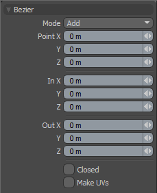
Mode: The various bezier curve mode options available are--
Add-- The default mode, when users click in the viewport, additional points are added to the curve. At each control point position two handles extend out that allow users to adjust the curvature of the curve segment between vertices. While drawing users can hover over any point or handle where it will turn yellow, users can then LMB+click and drag the control point or handle to further edit the curve. Control points may be added mid-curve by selecting the preceding control, highlighting it yellow, and clicking the position where the new control point is desired (point order is defined by the initial order in which the curve was created, press the 'F' key prior to activating the tool will invert the order).
Edit-- In edit mode users can freely LMB+click drag and of the control points or handles along the curve to change the look to the desired shape. While pressing the 'Ctrl' key, users may break the tangency of the control handles, allowing for sharp corners.
Delete-- In delete mode, users can LMB+click on any control point along the curve to remove it from the bezier.
Point X/Y/Z: Users wishing finer point control can assign specific XYZ values in these input fields for the currently selected (highlighted) control point.
In X/Y/Z/Out X/Y/Z: Users wishing finer handle control can assign specific XYZ values in these 'In' and 'Out' input fields for the currently selected (highlighted) control point.
Closed: The 'Closed' toggle option adds an automatic curve segment between the first and last control point positions producing a closed curve.
Make UVs: This toggle activates auto-generation of UV texture coordinates along the curve. The generated UV values will be of a single vertical line ('V' axis in UV) positioning all the control point vertices evenly between 0 and 1. For example, this can be useful for applying a Gradient to a rendered curve (the 'Render Curves' option is available in the 'Mesh' Items properties.

