
modo offers the powerful ability to create relationships between items channels when animating, allowing users to procedurally control elements without needing to add specific keyframes. The addition of constraints and modifiers extends that functionality allowing users to, for instance, force certain items to always face the camera, or to keep an element centered between two others. The Schematic viewport brings all of that functionality together into a unified environment, so users can visually link elements, including constraints and modifiers, providing a more intuitive and powerful way to build and rig animated scenes. The Schematic viewport is used in conjunction with the Channels viewport, and works by linking channels together via drag and drop.
Navigating the Viewport
The default Schematic view's use is similar to that of the UV view, where users are viewing and working with a flat 2D representation of the information. Users can navigate the view of complex assemblies by way of the navigation widgets in the upper right corner. LMB+click and drag on the arrow widget pans the view, while clicking the magnifying glass widget zooms the view. Users can also use keyboard familiar shortcuts to navigate, Ctrl+LMB+click and drag to pan, and Ctrl+Alt+LMB+click and drag to zoom.
Adding and Arranging Elements
When first opening the Schematic view, users are presented with a blank workspace, modo needs users to first tell it what elements they wish to work with and link. To add the necessary elements to the schematic view, users can use drag and drop functionality, dragging any item from the 3D viewport, Item List, etc. and dropping it directly into the schematic view adding the dropped element to the schematic. Users may also simply select the item(s) with the 3D viewport (or the Item List) and LMB+click the 'Add Selected' button at the top of the viewport. Once items have been added Node representations will appear in the viewport for each element, but only the elements themselves are represented. Users also need to add the appropriate channels for those particular items to actually create links. Users can do this by selecting the appropriate channels in the Channels viewport and drag and drop them onto the schematic view. They don't need to be dropped onto any particular item, anywhere over the window is fine to add them. Items and channels can be added at any time. TO remove a node, use the context menu, by RMB+clicking on the node header and choosing the remove node option or by selecting the node and pressing the 'Backspace' key.
User will find it easier to work with elements by organizing them and arranging them in the view. This can be accomplished by LMB+click on the node header and drag to move, then releasing the mouse button to position the element. modo will try to snap positions to surrounding nodes to make it easier to place and align nodes for an orderly schematic.

TIP: When adding items to the schematic view, if channel links or custom channels are already present, these will be added under the 'Header' node for their associated item.
Defining Links
To create a link between channels simply click and drag on an output connector (the round dots to the right of the channel name) with the left mouse button. A link will be drawn as the mouse is moved. Move the mouse over a channel's input connector (the round dots to the left of the channel name), it will turn green if the link is allowed, release the mouse button to create the link. Any incompatible channels are drawn disabled to indicate that a link cannot be made when the user drags over them. To delete links, LMB+click on the linking curve itself to select and press the 'delete' key. Users can simply move node links once created by LMB+click and drag the yellow connector dot and dragging it to a new position.
If there's a link to or from an item or channel that's not present in the view then a yellow circle is drawn around the channel connection dot. To load MMB+click on the channel dot to reveal. To quickly see where the link is from, or going to, position the mouse pointer over the connection dot and a tooltip will appear listing the connected channel(s). Channels that are not present in the view are enclosed in brackets. Note that only a maximum of five channels are shown for readability. If there's more than five links the number of channels not shown is appended at the end of the list. To add the channel to the view MMB+click the connector. This will add all the channels that are linked to it.
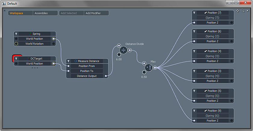
There are two main areas of the Schematic viewport 'Workspace' and 'Assemblies' defined by the mode buttons in the upper left corner. The 'Workspace' is an area in which users can experiment with setups and examine existing scenes. Any rigs, or portions of rigs, created in the Workspace may be extracted into individual assemblies, covered further below.
When the 'Assemblies' button in the toolbar is clicked on the view changes to show all the root level assemblies created in the scene, i.e. those that have no parent assemblies. The assemblies can be re-arranged by drag and drop same as nodes, drag an assembly and drop it in the gap between another assembly. Dropping an assembly onto another will cause it to become a child of the assembly it was dropped on. Assemblies that have a hierarchy beneath them have a small 'badge' drawn in the lower right corner of the assembly graphic which when clicked switches the view to show the complete hierarchy, allowing quick navigation between the child groups. Alternatively the 'hierarchy' button in the toolbar can be used.
In the Groups viewport users can see an option for 'Assembly' Groups, these are the groups that are displayed in the Assembly mode of the schematic view, new assemblies can be created via the 'New Group' button. This will create a new blank display in the schematic. The schematic always shows the most recently selected assembly group.
The contents of an assembly, or sub-assembly, can be viewed by double clicking on them. This shows the contents of the assembly and can be identified by the border that's drawn around the nodes. To each side of the display there are sidebars drawn in a darker shade. These contain any exposed input channels (to the left) or output channels (to the right). Clicking on the 'Add Channel' button in these areas will create a channel on the assembly which can be used as inputs or outputs to the assembly contents. If the assembly being viewed is part of a hierarchy, or a sub-assembly, the button in the toolbar with an arrow pointing upwards will allow you to view the immediate parent assembly. The toolbar button with the downwards pointing arrow will cause the view to change to the contents of any selected sub-assembly.
Creating Assemblies
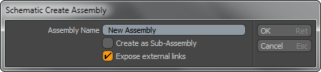
Once the user has a rig or even a portion of a rig setup, an assembly can be created from it. This is a good way of separating out parts of a rig for organization, allowing users the ability to work on each area independently, or to create a useful asset that can be saved out and re-used later. To create an assembly select each of the nodes you want to include and then right click on the background and choose "Create Assembly…" from the context menu. Provide a name in the dialog that's displayed. The new assembly can be created in two ways, as a normal assembly or as a sub-assembly, determined by the "Create as Sub-Assembly" option. When enabled this option will create an assembly that becomes part of the current group, otherwise a standalone one will be created. In both cases the selected nodes are removed and added to the new assembly. The last option, "Expose External Channels" is only applicable to sub-groups, this will create channels on the new group for each channel link to or from a channel within the group. This is very useful for creating assemblies that can be re-used elsewhere, a kind of 'black box' that can be connected up without knowing about the internals. When you click 'OK' the new assembly will be created, if it was a standalone assembly the view will change into the 'Assembly' view to show it's contents.
Creating Sub-Assembly Walk-through
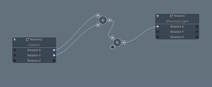
Select the elements that make up the sub assembly, here it is the 'add' and 'multiply' nodes.
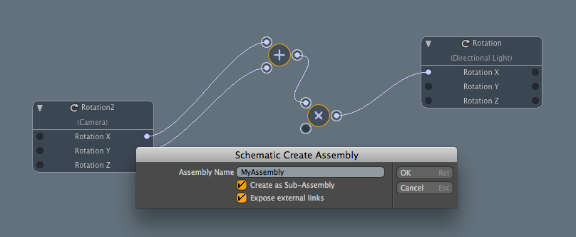
RMB+click on an open area of the workspace and choose 'Create Assembly' from the context menu.
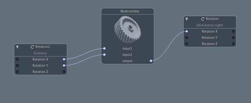
Clicking 'OK' changes the selected elements into the Sub-Assembly.
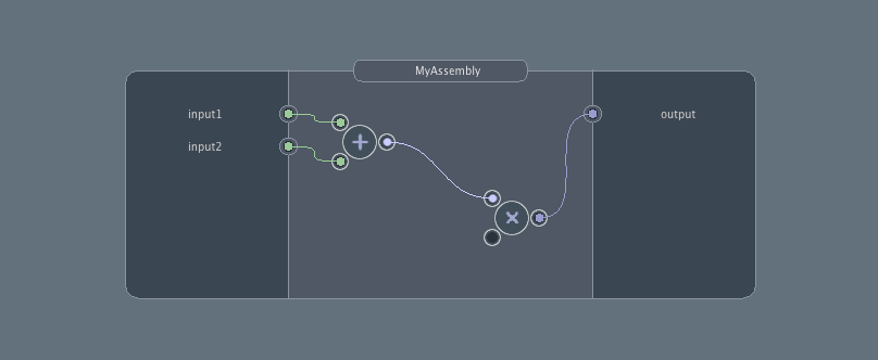
The contents of any Sub-Assembly can be viewed by LMB+double clicking on the node.

