
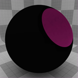
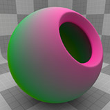
The Gradient texture layer is an incredibly powerful asset in the shading arsenal. Gradients provide a method for creating parametric materials. Put simply, gradients remap colors or value based input parameters the user defines and produces an output based on the values in the gradient itself. For instance, with a gradient texture you could tell a surface to ramp from purple to light blue based on the incidence angle to the camera or purple to green based on the slope of the surface. You can even control the number of clones in a replicator based on height and angle of a surface. Gradients are also useful in controlling the color of fur, and replicators. With so many options, it can feel a little overwhelming; the following samples should help ease any confusion regarding a particular gradients use.
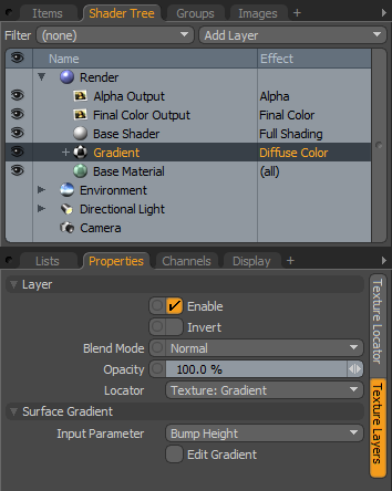
Gradients are added to the shader tree where it is indicated the 'Effect' it will have on the surface, such as Transparency or Diffuse Color. Next, users will need to select the 'Input Parameter' on the Gradient textures properties panel, this defines how the gradient modulates the surface it is affecting. By clicking the 'Edit Gradient' check box users can open the Gradient Editor where the actual gradient is defined. Its usage is covered below. For additional information on adding and using layers, please reference the Shader Tree page of the documentation.
 Layer--
Enable: Toggles the effect of the layer on and off, duplicating the functionality of toggling visibility in the Shader Tree. When un-checked (disabled), the layer has no effect on the shading of the scene. However, disabled layers are saved with the scene and are persistent across modo sessions.
Invert: Inverts the RGB values for the layer producing a negative effect.
Blend Mode: Affects blending between different layers of the same effect type, allowing user the ability to stack several layers for different effects. For more on blending, please reference the 'Blend Modes' page of the documentation.
Opacity: Changes the transparency of the current layer. Reducing this values will increasingly reveal lower layers in the shader tree if present, or dim the effect of the layer itself on the surface.
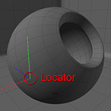
Locator: Gradient layers always have an associated 'Texture Locator' that is automatically created in the 'Item List'. While they typically define the mapping of the texture (way the texture is applied) to the surface, for gradients, the mapping is largely defined by the input parameter. The Locator option in this instance is necessary to select the appropriate locator to control input parameter effects such as Distance to Locator and Locator Incidence. Within the locator, users may specify UV maps and such useful for other parameters.
Surface Gradient--
Input Parameters: There are many different input parameters to choose from which makes the Gradient texture incredibly powerful.
Back Facing-- When set to 'Back Facing' the gradient will color both the front and rear sides of a polygon. The Color or Value at the 0% position shades the front of the polygon, while the Color or Value at the 100% position shades the the opposite side of the polygon. Users will first need to enable the 'Double Sided' option in the Material item to see the results of this Gradient Parameter.
 Gradient |
 Back Facing |
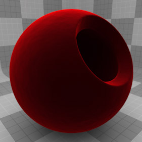
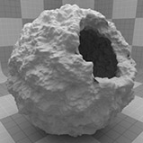
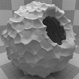
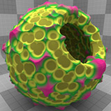
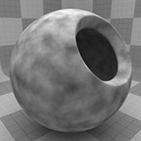
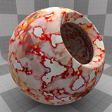
Bump Height-- When set to 'Bump Height' the Gradient is driven by any Bump Map textures that are effecting the same material and the input value becomes a percentage where 0% is the lowest area of the bump texture and 100% is the highest peak. If there are no texture layers driving the bump map effect the Gradient will be disabled.
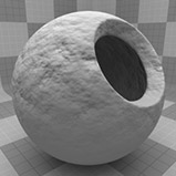 Noise Bump Map |
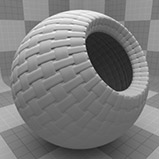 Weave Bump Map |
Gradient |
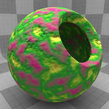 Bump Height Gradient |
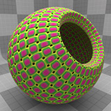 Bump Height Gradient |
Distance to Camera-- Modulates the value as a function of the physical distance to the camera measured from its center point. This opens a lot of interesting possibilities, such as adding fog like effects or fading luminosity as the surface gets further from the camera. Keep in mind a gradients layer isn't strictly limited to affecting Diffuse Color.
Gradient |
 Distance to Camera |
Displacement Height-- Similar to Bump Height, this input parameter is driven by a Displacement texture layers directly below the Gradient in the Shader Tree and maps itself along the the displacement height amount. 0% at the lowest displacement area, and 100% at the maximum displacement amount. Negative gradient values may also be necessary for remapped displacement values (i.e. changing the low/high values in the texture item to -100%, 100% respectively).
 Displacement Map |
 Displacement Map |
Gradient |
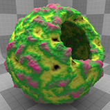 Disp. Height Gradient |
 Disp. Height Gradient |
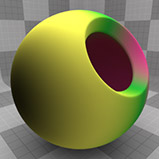
Distance to Locator-- Very similar to the Distance to Camera parameter, the Distance to Locator modulates the gradient based on the position of the items texture locator, specified by the 'Locator' option above.
 Item Locator Position |
Gradient |
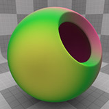 Dist. to Locator |
XYZ Distance to Locator-- Creates a distance based linear gradient that runs along either the X, Y or Z axes as specified, with the gradients origin controlled by the position of the items texture locator, specified by the 'Locator' option above..
Item Locator Position |
Gradient |
 X Distance |
 Y Distance |
 Z Distance |
Driver A, B, C, D-- The 'Driver' settings will read any Texture item or combination thereof, whose 'Effect' is set to the same Driver letter (A,B, C or D). This allows users to have texture layers that can drive Gradients very easily. It also allows users the ability to remap the tones of a texture layers by using the gradient. Users should note that when using colored bitmap textures to drive the gradient, the brightness, or luminosity of the image will be the actual driving property. Users should also note that the gradient needs to be above the driving texture in the shader tree and that the letter value of the texture items 'Effect' needs to match the gradients 'Input Parameter' value (for example, both would need to be set to "Driver A' for it to work).
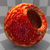 Image Map Driver |
 Procedural Driver |
Gradient |
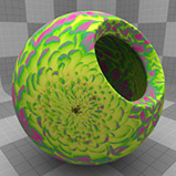 Image Map Grad. result |
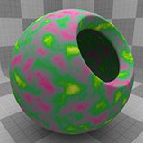 Procedural Grad. result |
Group Mask-- When the Gradient layer items 'Input Parameter' is set to 'Group Mask' and the 'Effect' is set to the same, a gradient can modulate any texture layers themselves set as 'Group Mask (within the the same group, of course). When the 'Effect' is set to anything else, the Gradient is driven by the Group Mask items, much like the Driver input parameter, overriding the effect of the mask on the group.
 Base Group Mask |
 Stepped Gradient |
 Modulated Mask |
Fur Parametric Length-- This drives gradient values along the length of individual fur fibers, 0% at the root, to 100% at the tip. Frosted tips? Sea anemones? No problem.
Gradient |
 Fur Length |
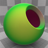
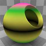
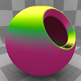
Incidence Angle-- This is the angle between the camera and the surface being evaluated. Surfaces that face the camera head on have an incidence angle of 0° (0%) while the edges that face away (perpendicular) to the camera have a value of 90°(100%). This setting is often used to simulate the Fresnel effect as well as simulate the look of velvet surfaces.
Gradient |
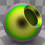 Incidence Angle |
Layer Mask-- The 'Layer Mask' will work identically to the 'Group Mask input parameter, but where a Group Mask affects an entire group, a layer mask only affects a single layer. Setting the Gradient layers 'Effect' to 'Layer Mask', the gradient will modulate the texture layer directly below when set as 'Layer Mask'. When Gradients 'Effect' is set to anything else, the Gradient is driven by the Layer Mask items, much like the Driver input parameter, overriding the effect of the mask.
Base Layer Mask |
Stepped Gradient |
Modulated Mask |
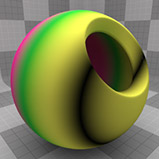
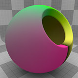
Locator Incidence-- This parameter is identical in effect to incidence angle but can be controlled by a locators position instead of fixed to the cameras point of view.
Item Locator Position |
Gradient |
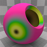 Locator Incidence |
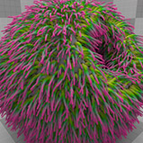
Particle ID-- When Fur fibers and Surface Generator replicas are created, each is assigned a random Particle ID value between 0 and 1. When a Gradient is applied with the Particle ID input parameter, each fiber or replica will pull a value from the gradient based on that randomly generated ID offering users the ability to create controlled randomness. Now generating 'salt and pepper' fibers for a Fur Material is as easy as pie.
Gradient |
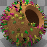 Replicator Particle ID |
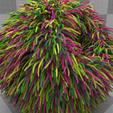 Fur Particle ID |
Slope-- This is simply the angle of the surface normal as compared to the World axes. 0° straight up is 0%, and 90° perpendicular is 100%
Gradient |
 Slope |
Texture U/V-- The Gradient will read the texture coordinates from the UV map and modulate the Value based on the 'U' (horizontal) or 'V' (vertical) value of the map.
Gradient |
 Texture 'U' |
 Texture 'V' |
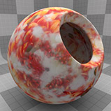
Texture Value-- This setting will apply the Gradient across the values of any texture layer directly beneath it regardless of that texture's 'Effect', 'Blending' or 'Opacity' settings.
Image Map Texture |
Procedural Texture |
Gradient |
Image Map Grad. result |
Procedural Grad. result |
Edit Gradient: Check this box to open the gradient editor. This is where the actual gradient is created (see below).
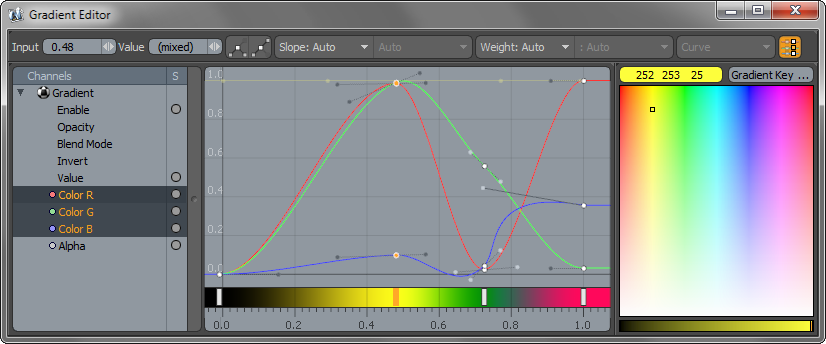
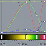
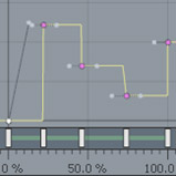
The Gradient Editor is where users define the actual Gradient values. Though visually and functionally similar to the Graph Editor, the Gradient Editor assigns values over a range instead of over time as the Graph Editor does. Users will typically only be concerned with the R,G & B color, Alpha and Value channels. Modifying other attributes reverts the bar to a timeline where values are modified over time.
The window itself is divided into several sections.
Across the top are the numeric input text fields followed by key controllers. These allow users to apply specific values to a key as well as control the slope of incoming and outgoing curve handles. The left side of the window displays the channels available for editing. modo will generally select the appropriate channel based on the layers 'Effect' setting, but user can select 'Value' or 'RGB Colors' based on the layers intended use. The center window is where users define the keys and modify their positions. New keys are added by MMB+clicking in the graph area at the position where the key should be created. Once set, users can modify the key LMB+clicking in the color palette on the right side. Positions of keys can be modified interactively by simply clicking on the individual handle bases (the white dots along the curves) and dragging them around in the viewport. Key positions can also be modified by dragging the handles that appear in the gradient bar below the graph area.
Channels--
From within the channel section, users can select the value they wish to modulate. For diffuse color this would be the 'Color R,G and B channels, for specular amount, this would be the 'Value' channel. Once selected, a line representing the value appears in the graphing window.
Setting Keys--
Keys can be added to the currently selected curve(s) by MMB+clicking either on the curve itself or anywhere on the graph area background.
Setting Colors for Keys--
The color of selected keys can be set or adjusted by selecting the color key and either LMB+clicking and dragging on the Color Picker viewport or from the RMB context menu. Selecting 'Key Color' from this menu will open the Color Picker from which a color may be chosen. In both cases additional keys may be created on associated curves at the key Input value.
Deleting Keys--
Keys can be deleted from curves in two ways, to delete only the currently selected keys press the 'Delete' key. To delete the currently selected keys and keys at the same Input value on associated curves select 'Delete Key' from the RMB context menu.
Selection--
LMB - Selects a key under the cursor, holding the Shift key while selecting adds to the selection, and holding the Control key removes a key from the selection set. Clicking on the background deselects all keys.
LMB & Drag on the background starts box selection, drag out a box to enclose the keys you want to select and release the mouse button. All keys within the box will become selected, any outside the box will be deselected. Holding down the Shift key adds the keys within the box to the selection while the Control key removes them.
LMB click on a curve in the background (dimmed) will select the curve. Curves can be added to the selection by holding down the Shift key and clicking on a curve and can be removed from the selection by using the Control key.
Curves may also be selected from the menu at the top left of the viewport, this menu lists all the curves associated with the currently selected Gradient item(s).
Editing--
LMB & Drag on a key selects the key if it's not already selected and allows quick editing of both Input & Output values at the same time. If there are several keys already selected and you click drag on one of them then all the selected keys will be modified.
MMB & Drag on a key works in a similar way except that editing is constrained to the Output value. Similarly RMB & Drag constrains the edits just to the Input Parameter value.
MMB & Drag vertically on the background adjusts the Output value of all selected keys.
RMB & Drag horizontally on the background adjusts the Input value of all selected keys.
Control-MMB & Drag on the background provides constrained editing of Input & Output values for selected keys based on the initial direction of movement.
LMB Double click on a key selects all the keys on the curve.
Context Menu--
The Gradient Editor context menu is accessed by RMB click & release. If the cursor is over an un-selected key when the menu is opened the key will be added to the selection. Operations performed from the context menu will affect all the currently selected keys.
Navigation--
Panning & Zooming behavior in the Gradient Editor is similar to the 3D viewports with a few additions:
Alt-MMB Drag adjusts the start value of the Input (horizontal) range displayed in the editor, while Alt-RMB Drag adjusts the end value of the Input Range.
Alt-Shift-MMB zooms the Output Range displayed in the editor, while Alt-Shift-RMB zooms the Input Range. In both cases the zoom is centered on the initial cursor location.
Alt-Control-RMB provides box zooming.
Mouse Wheel - Zooms in and out around the cursor location.

