
The 'Raycast' node adds the ability to fire rays based on user defined criteria, gather information from where the ray hits (or doesn't hit) and then use this information to drive other channel values. For example, the Raycast node makes it possible to make a virtual camera for a scene; what it sees (the results of the ray evaluations) would be displayed on another surface elsewhere in the scene, determined by the output connections.
To create a ray, you need to have both a position and a direction, these can be a specific defined vector value or be representative of shading values within the scene (such as a position and normal sample from a surface using a Shader Input connection). The inputs are connected to the 'Origin' and 'Direction' and represent the ray that is fired for sampling, and are evaluated per sample. If nothing is connected to these inputs, the current sample position and/or ray direction is used.
. Once the sampling ray is defined it is also necessary to specify what the ray should 'see' in the scene, either polygons, volumetrics, etc. These options are defined in the 'Properties' panel when the node is selected. Once the target for sampling has been hit, it needs to be determines what is sampled from the hit- Shading, Bump/Normal and/or Opacity. The results of what the ray samples are then returned to the various outputs on the node. These values can then connected to the input of another channel, driving its value.
Usage
The Ray Cast node is added to the 'Schematic Viewport' using the 'Add' function, found in the popup menu under "Shader Inputs > Ray Type". There are no specific inputs for the node, but each type of selected ray is evaluated automatically for each sample and returned to its specific output. For information on working with node graphs, please reference the Schematic Viewport documentation for additional information.
Raycast Item--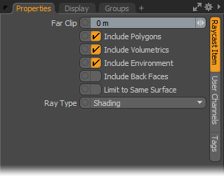
Far Clip: The 'Far Clip' option controls the maximum sampling ray length. When set to '0', the ray will not be clipped (infinite ray).
Include Polygons: This toggle determines if 'Polygons' will be sampled by the defined ray, this includes all the geometry in the scene.
Include Volumetrics: This toggle determines if 'Volumetrics' will be sampled by the defined ray, including 'Blobs', 'Volumes' and 'Sprites'.
Include Environment: This toggle determines if the 'Environment' will be sampled by the defined ray (The environment is the result of not hitting anything else in the scene).
Include Back Faces: This toggle determines if 'Back Faces' of polygons will be sampled by the defined ray.
Limit to Same Surface: This toggle limits the sample made by the Raycast node to the same surface the ray is cast from (adjoining surfaces would be ignored, per surface of course).
Ray Type: The Ray Type option determines the type of sampling ray that is generated by the node-
Shading- Samples the fully shaded position, including Diffuse, Specular, and Reflection and the illumination on the surface.
Shadow- Samples if position is illuminated or in Shadow.
Material- Samples material Diffuse Color value only, ignoring the additional shading contributions.
Normal- Samples the shading normal, including perturbations of the ray caused by Bump Maps, Normals Maps and Displacement.
Schematic Node: Raycast
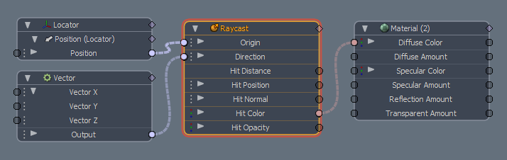
Origin Input: This input channel determines the origin of the sampling ray that is fired for scene evaluation.
Direction Input: This input channel determines the ray direction of the sampling ray that is fired for scene evaluation.
Hit Distance Output: This output channel represents the length of the ray that is fired, defined by its sample origin position to the hit surface (this doesn't include the distance from the camera to the sampling position)
Hit Position Output: This output channel represents the position in 3D space where the ray 'hit' occurs.
Hit Normal Output: This output channel represent the evaluated normal direction of the hit surface.
Hit Color Output: This output channel represent the evaluated color of the hit surface.
Hit Opacity Output: This output channel represent the evaluated transparency of the hit surface.

