
The 'Render' Item always occupies the top spot in the shader tree, this is no mistake considering its importance. The Render item can be thought of as a general container for global scene render settings. When the Render item is selected, its various attributes become available in the Properties viewport. It is broken into three subtabs of related settings. The 'Frame' tab allows users to adjust render settings specific to the rendered frame itself such as its dimensions. The 'Settings' tab allows users to adjust render settings specific to rendering quality such as anti-aliasing. The 'Global illumination' tab allows users to adjust render settings specific to Global Illumination, a rendering technique that utilizes bounced light to produce incredibly realistic rendered images.
Settings
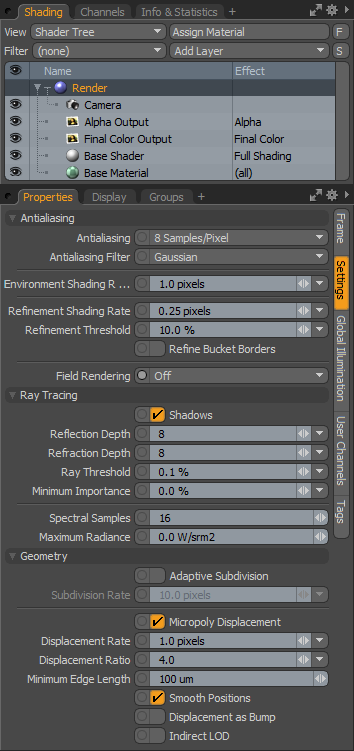 Antialiasing--
There are three main settings that control the "quality" of rendered pixels. These include Antialiasing, Refinement Shading Rate and Refinement Threshold. To create the highest quality imagery MODO does all of its computations at the sub-pixel level; taking multiple tiny samples within the space of a single pixel and then averaging their result. However, rather than computing the entire image this way over and over; the "brute force" method, MODO uses elegant logic to determine how to best create the image. To balance quality with performance MODO provides methods to determine which areas of the image should receive the greatest number of samples.
Antialiasing: At the top most level the Antialiasing control dictates the numbers of "samples" taken per pixel. MODO allows you to specify from 1 to 1024 samples per pixel in powers of 2 (1,2,4,8,16 and so on up to 1024). We can think of these samples as sub-pixel fragments; imagine a pixel as a square that can be divided into smaller squares. When Antialiasing is set to 8, the pixel is broken down into 8 pieces, each of these pieces is evaluated and then averaged together to give us the final high-quality pixel. Since it would be expensive time wise, and overkill, to evaluate every single pixels in an image repeatedly we have some additional controls to limit the areas that receive the maximum number of evaluations.
Antialiasing Filter: This popup option allows you to choose different antialiasing filters. The antialiasing filter determines the pattern to use when evaluating a pixel. The default is 'Gaussian' which performs very well in most cases and offers a good balance of performance and quality. Box, Triangle, Catmull-Rom and Mitchell-Netravali are additional options. Catmull-Rom will generally yield slightly 'sharper' results than Gaussian while Mitchell-Netravali offers good results when dealing with problematic moire created by fine texture patterns.
Environment Shading Rate: This option specifies the approximate spacing between shading samples measured in pixels, used for the environment. It also acts as a cap on the rates specified in the various shader items, allowing shading detail to be increased across the entire frame. The main reason one would want to lower this value would be to improve the motion blur of volumetrics. (In previous versions of MODO this option was called the 'Coarse Shading Rate').
Refinement Shading Rate: The 'Refinement Shading Rate' control tells the engine how finely to evaluate any pixel that falls within the 'Refinement Threshold'. When a pixel is being evaluated, first, it is rendered through the standard 'Antialiasing' application, neighboring pixels are then tested for 'Refinement Threshold'. If a pixel is within the threshold, then the pixel is finished and the engine moves on to the next, but if it is outside of the threshold, then the 'Refinement Shading Rate' kicks in, and the pixel is further evaluated. The value itself basically acts a as a multiplier of the pixels size, so a setting of .5 would split the pixel in half both ways resulting in 4 additional shading samples calculated, a setting of .1 would split the pixel 10 times both directions resulting in 100 additional shading samples calculated, overkill in most cases.
Refinement Threshold: The Refinement Threshold is essentially a contrast tolerance which is to say this control dictates how much contrast between adjoining samples is acceptable. Set to 100% the Refinement Threshold would do nothing at all as it would accept brightness steps as high as 255 (the upper bound of a 24 bit image). Set to 0% no pixels would be inside the threshold and every pixel would be refined. The percent amount spans the 0 to 255 brightness steps so a threshold of 50% would accept pixel contrasts of 128 steps whereas a setting of 10% would only tolerate 25 brightness steps between samples. Just like the refinement shading rate, we see that an increase in quality when set to lower values, but it also increase computation requiring longer render times.
Refine Bucket Borders: Due to the 'bucket' nature of MODO's render engine, adjacent pixels in neighboring render buckets can't be used to decide whether a border pixel needs further refinement because they are either not rendered yet, or fully rendered and no longer active. By enabling 'Refine Bucket Border' MODO will tell MODO to assume all border pixels in a given bucket require refinement.

TIP: The Antialiasing setting's effect is most apparent on geometric edges, a setting of 8 is generally acceptable and is a good trade off between quality and speed, though in reproducing effects such as 'Depth of Field' or 'Motion Blur' you will need to increase this value possibly all the way up to 1024 to produce a pleasing result. If you find your shaded edges, such as cast shadows, refractions, reflections, procedural and image based textures are aliased (not smooth), then reducing the shading rate value or lowering the refinement threshold will help to increase shaded edge quality. If you are finding specific areas of an image to be noisy, that cannot be solved by Antialiasing and Refinement, such as soft reflections, blurry refractions, soft shadow edges, subsurface scattering, it may simply be a case where raising the number of samples specific to the effect will eliminate the noise. These setting can be found in the associated properties panels. Always keep in mind though, as more calculations are taken into account, the longer an image will take to render.
Field Rendering: For scanline televisions (older tube televisions) there were originally two half frames that made up each whole frame, interlaced on top of each other to make a single image. Enabling the 'Field Rendering' option will properly render two discreet moments in time and interlace the resulting half-frames into a single image (in essence doubling the frame rate). This option is useful to compose MODO generated elements into video that was originally captured this way. When using Field Rendering, it is recommended that users switch to 'Box' antialiasing to eliminate field cross-talking. Also, post effects, such as 'Bloom' will be generated on a whole image basis, so should only be applied in a compositing package. Modern film and video capture is largely progressive, where each frame represents only a single moment of time, so in most cases Field Rendering will not be necessary.
Ray Tracing--
Shadows: Enabled by default, the 'Shadows' checkbox directs MODO to globally render all shadows cast by direct lights. Direct lights can be any of the light items, such as Distant Lights, Area Lights, Point Lights, Spot Lights, Dome Lights Cylinder Lights, and Photometric Lights. Shadows cast by luminous polygons when Global illumination is enabled are not affected by this setting (their shading is part of the indirect illumination). Shadows can be disable on a per light basis in each lights properties panel, by setting shadow type to 'none'.
Reflection Depth: MODO renders images by ray tracing, sort of like shooting tiny arrows out from the cameras lens and seeing what they hit. If a ray hits an object that is reflective, that ray bounces off the object until it hits another, should that surface also be reflective MODO will again bounce that ray until it finds a surface that is not reflective. If the ray doesn't find a surface that isn't reflective, the 'Reflection Depth' threshold stops the ray from continuing on its path keeping MODO from infinitely tracing rays between reflective surfaces. The default of 8 bounces in fine for most scenes, and is a good compromise between render accuracy (quality) and render time. In some instances you may find a need to increase this setting to accurately portray all the reflective surfaces in a scene, or find you need to reduce it to shorten render times.
Refraction Depth: Refraction Depth, like Reflection Depth is calculated by ray tracing. When a ray enters a refractive surface with some transparency, the ray bends the appropriate amount and travels until it hits its next surface, if that surface is also refractive, again the ray is bent and sent along its path until it hits a non-refractive surface or is stopped by the Refraction Depth threshold from traveling further. The default setting of 8 is often good enough for most scenes and is a good compromise between render accuracy (quality) and render time. In scenes with many transparent surfaces, you may find a need to increase the setting to accurately portray all your transparent surfaces, or find that you need to reduce it to shorten render times.
Ray Threshold: For some scenes, firing all those refraction and reflection rays can get expensive time-wise. What if there were a way to eliminate those rays that have little to no impact on the final rendered image, but are just as expensive to calculate as the rays that are important? Ray threshold does just that. As rays are fired, they are given an importance value that can decrease or increase at each bounce depending on the surface values contribution. Should the rays importance fall below the 'Ray Threshold', MODO randomly decides to kill the ray or trace it further (up until the total depth value specified). This random killing of rays reduces the overall number and depth of rays traced but has little visual impact on the final image. Increasing the Ray Threshold value will further eliminate rays, though at the expense of image quality.
Minimum Importance: Importance is an estimate of how much a particular shading evaluation will contribute to the final color of a pixel. For surfaces directly viewed by the camera, it's basically what fraction of a pixel the shading evaluation represents, which depends on how many antialiasing samples are being shaded together as part of a single evaluation versus the total number of antialiasing samples in the pixel. If there are eight AA samples in a pixel and they are all shaded together as a group (which can happen if they all belong to the same surface and the Shading Rate is large), that single shading evaluation entirely determines the pixel color and thus has an importance of 100%. At the other extreme, if each antialiasing sample is shaded separately (which can happen if the Shading Rate is small or zero), then each of the eight shading evaluations will have an importance of 1/8 or 12.5%. This importance value is used to modulate the number of rays used to compute various phenomena such as soft shadows, Monte Carlo indirect illumination, blurry reflections, etc. At 100% importance, the full number of rays specified will be used. For example if there are 64 blurry reflection rays specified in a material's properties, then 64 rays will be fired during the shading evaluation. But in a shading evaluation with 12.5% importance, only eight reflection rays (12.5% of 64) will be fired.
The 'Minimum Importance' setting imposes a lower limit on importance when shading surfaces directly viewed by the camera. This can cause more rays to be used in some cases, reducing artifacts which can be caused by Clamp Colors but can also possibly increasing render time.
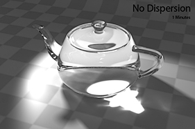
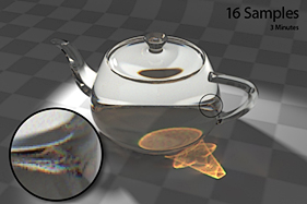
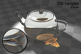
Spectral Samples: When rendering any transparent refractive surfaces with 'Dispersion', the 'Spectral Samples' value determines the number of rays that each dispersion ray is broken into. The higher the number of rays, the smoother the dispersion calculations will be, at the expense of longer render times.
|
|
|
Maximum Radiance: This option controls the maximum radiance carried by a ray, limiting it to a user defined value. This can be helpful in reducing noise and preventing fireflies (single bright pixels) caused by small but very bright features of a scene, such as tight specular highlights or surfaces very close to point light sources. Setting the Maximum Radiance to '0' (zero, the default value) means that a ray can carry unlimited radiance.
Geometry--
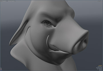
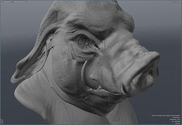
The first two settings under the Geometry section are global controllers that relate to Subdivision Surface (SDS) models in a scene. 'Subdivision Surfaces' is a means of producing a smooth continuous mesh at render time based on a low resolution proxy model (sometimes called the 'Cage; or 'Limit Surface'). Generally, when straight polygon modeling, surfaces are made from 'faces', each its own tiny flat plane that when shaded together simulates a smooth surface, but silhouette edges can reveal the faceted nature of the model. The traditional fix for this limitation is to simply add more polygons, but controlling all those real polygons can quickly become unwieldy. For a SDS model, the polygons in the low resolution model are automatically divided and refined recursively in such a way that the resulting model is a smooth organically curving surface.
In MODO, users can toggle any object as a SDS model by simply pressing the 'Tab' key. Users can control the level (number of times the models is subdivided) using the 'Subdivision Level' setting found in the mesh item properties viewport. Higher values will produce smoother models, but generate more geometry that requires more processing time and memory to render. When the 'Adaptive Subdivision' setting is enabled, this function will override the mesh item setting at render time allowing users to adaptively control all the Subdivision Surfaces in a scene globally.
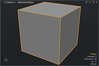 Original 'Cage' Geometry | 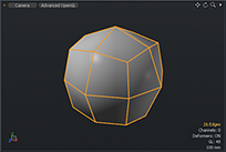 SubD level of 1 | 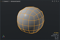 SubD level of 2 | 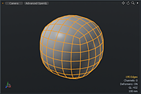 SubD level of 3 |
Adaptive Subdivision: This setting toggles the 'Adaptive Subdivision' function in MODO. When enabled, MODO will adaptively tessellate all SDS meshes at render time. Which is to say, depending on the users settings, the mesh is refined repeatedly until all polygonal edges fall within the users subdivision rate.
Subdivision Rate: When 'Adaptive Subdivision' is enabled, the subdivision rate sets the Level threshold for all SDS geometry in a scene. Defined as pixels, the default rate is 10, which means that MODO will pick a subdivision level for that mesh such that the length of edges for any group poly's in the largest subdivision patch appear no more than 10 pixels long (most will be shorter than that). This is very useful since it means that subdivision levels automatically adapt to each mesh's distance from the camera, the zoom factor, etc. If you really want to minimize your polygon count, you can set the subdivision rate to a huge number such as 1000. On the other hand, if you never want to see a faceted edge in a render you can reduce this number to 5 or less. Be warned that reducing the subdivision rate will be at the expense of additional system memory use and performance loss.
The next five settings control MODO's Micropolygon Displacement function, a means of adding fine geometric detail to surfaces by way of a texture based controller. Similar in nature to Subdivision Surfaces, polygonal surfaces are automatically divided and refined recursively producing finer and finer micropolygons that are then displaced (pushed in or out in the polygons normal direction) based on a grayscale value (and users settings in the Texture Locator item). This can result in an incredible amount of detail for models that would be difficult or impossible to create otherwise. Similar to a bump map, but where a bump map is a rendering trick that simulates detail on a surface and often looks off, displacement is actual geometry. 'Displacement' maps can be created in MODO using any of the painting or sculpting tools, generated in an external application and applied to the object, or simply applied as a procedural texture layers in the shader tree. For best results, users should enable SDS for any surfaces with displacement applied. Please reference the Texture Effects page of the documentation for more on working with displacement maps.
|
|
|
Micropoly Displacement: When an objects surface has displacement applied in the shader tree, this checkbox will toggle the rendering of micropolygon displacement on a global level.
Displacement Rate: When Micropoly Displacement is enabled, the 'Displacement Rate', sets the threshold to which the geometry is subdivided into micropolygons. Similar to the Subdivision rate, Micropolygon displacement is adaptive, evaluating every polygon edge separately. The distance from the camera to the center of the edge (the focal length), and the render resolution are used to convert the Displacement Rate (in pixels) into a distance in world space. If the edge is longer than this and also longer than the Minimum Edge Length, it is split in half. This process continues recursively until all edges satisfy those requirements.
Displacement Ratio: The 'Displacement Ratio' is the ying to 'Displacement Rates' yang. When set to 1.0, objects are tessellated a consistent amount across their entire surface, but when displacing large areas, such as a ground plane in an environment, where a good deal of the geometry lays outside of the view of the camera, most of those polygons are going to waste filling up your systems memory. The Displacement ratio reduces the number of displaced polygons outside the cameras view; the higher the number, the greater the reduction in polygons. Keep in mind though that reflective and refractive objects will still be able to 'see' these areas outside the cameras view, so high settings may begin to introduce artifact to your image.
Minimum Edge Length: Each edge in the mesh is tessellated until polygons satisfy the Displacement Rate setting. Ungoverned, this can go out of control resulting in ridiculous numbers of polygons. The Minimum Edge Length does exactly what the name implies. It sets a minimum length for any polygonal edge. Once an edge has reached that minimum length it can no longer be split. A simple and effective throttle for controlling the amount of polygons in your scene.
Smooth Positions: When a surface is diced into micropolygons, the initial positions of the micropolygon vertices lie on a curved surface based on the original smooth vertex normals. So if you start with a regular non-SDS sphere, for example, it'll be diced into a smooth sphere, and then the displacement texture will be applied to that. You could even use this as an alternative to subdivision surfaces by just applying a displacement texture that is zero everywhere (although the resulting surfaces are different from SDS in that they will actually pass through the original vertices). The ability to turn off position smoothing, which means that all the initial positions of the micropolygon vertices will lie exactly on the flat planes of the original polygons. Doing this in the non-subdiv sphere example would cause the diced version to look faceted. The reason this feature was added was that it's necessary to turn off position smoothing when using a displacement map created by object-to-object baking, since the distances in the map are measured based on the original polygons of the low-poly object and not the smoothed polygons.
Displacement as Bump: When this option is enabled, MODO will apply any displacement maps also as a bump map, providing a finer detail evaluation that requires lower number of subdivisions to achieve. This can be a great way to reduce the amount of memory necessary to render complex scenes when combined with lower subdivision rates.
Indirect LOD: When this option is enabled, MODO will hold an additional lower resolution version of displaced geometry used strictly in calculating Indirect lighting reducing overhead in GI calculation, however it may end up using slightly more memory as two distinct copies of the same geometry may be held in memory simultaneously.

NOTE: Highly triangulated surfaces, such as imported CAD models are not good candidates for micropolygon displacement.

