Rendering is the act of converting the scene information into a bitmap image by evaluating all the geometry and lighting information in a given file. Generally users will expect the resulting rendered image to be a fully ray traced and shaded image with full shadows, reflection and the like, much like a photograph depicts an entire scene when taking a picture with a camera. In MODO these images are the result of what are called "Render Outputs", the visible representations of the full scene evaluations. Each Render Output is a separate layer in the Shader Tree and will produce its own image layer as part of the render calculations. Every time a Render command is invoked, all of the render output layers are simultaneously calculated and represented in the Render Display viewport. The different layers can be viewed by choosing one of the specific 'Output' options within the display window.
Occasionally users will only want a subset of the full evaluations, such as the diffuse color layers without any shadows. MODO offers many different 'Render Output' types useful in a variety of situations ranging from purely diagnostic, to specific compositing utility in an external application. A default scene automatically includes a 'Final Color' and 'Alpha' output which should be fine for most situations. Additional layers can be added from within the shader tree viewport itself, by LMB-clicking the 'Add Layer' option of the full viewport window and selecting "Special >> Render Output" from the pop-up menu. This adds an additional layer to the top of the tree. Users may then RMB-click in the 'Effect' column of the Render Output for a pop-up context menu that allows one to select from the alternate output types. Please reference the primary Render Outputs page of the documentation listed under the Shader Tree Layers section for for information regarding the editable attributes of the individual outputs. Examples of the various output types available are as follows--
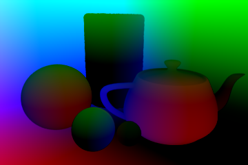
dPdu Vector
The 'dPdu' and 'dPdv' are world space vectors that point in the direction of increasing U and increasing V at each point on a surface that has a UV map. dPdu and dPdv have a big effect on the anti-aliasing of UV image maps and also define the reference directions for anisotropic highlights and reflections, so the outputs are sometimes useful for the purposes of debugging.
Dpdv Vector
The 'dPdu' and 'dPdv' are world space vectors that point in the direction of increasing U and increasing V at each point on a surface that has a UV map. dPdu and dPdv have a big effect on the antialiasing of UV image maps and also define the reference directions for anisotropic highlights and reflections, so the outputs are sometimes useful for the purposes of debugging.
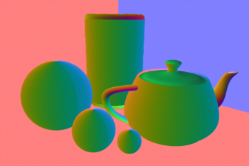
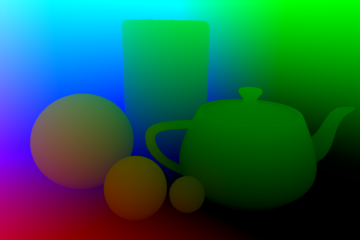
Geometric Normal
The 'Geometric Normal' output simply renders all meshes with a color ramp based on the angle of their polygonal normal, where the RGB image components represent the corresponding XYZ vectors, so values will be negative unless the 'Normalize' option is enabled. It is useful for evaluating the continuity of a mesh's surface. In this example the Material Item 'Smoothing' option has been disabled to emphasize the effect.
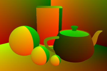
Object Coordinates
The 'Object Coordinates' output generates red, green, and blue components that contain the undeformed object space X, Y, and Z coordinates of visible surfaces. The pixel values are in meters and can be negative, so a floating point image format should be used when saving this output. This theoretically allows post-processing applications to add solid textures that will remain attached to surfaces during an animation.
Segment ID
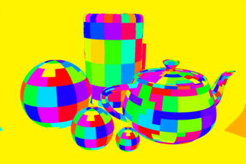
When MODO renders a project, all meshes are broken down into "segments" for reasons of optimization and general scene management. Using the 'Segment ID' shading option will render each generated segment with a random color. This shading method is purely a diagnostic option.
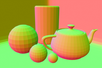
Shading Incidence
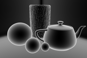
The 'Shading Incidence' output renders a grayscale image the represents surfaces angle relative to the camera. Shaded surfaces that face directly at the camera are rendered as black attenuating toward white on shading that is perpendicular to the camera.
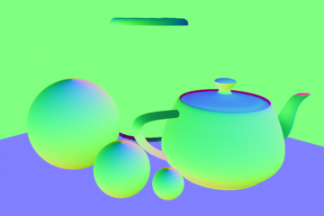
Shading Normal
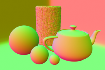
The 'Shading Normal' output renders all meshes with a color ramp based on the angle of their surfaces shaded normal where the RGB image components represent the corresponding XYZ vectors, so values will be negative unless the 'Normalize' option is enabled. Where the Geometric Normal is calculated exclusively by the polygonal geometry, the Shading Normal also takes in to account surfacing attributes affect on normals such as Bump maps.
Surface ID
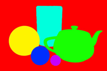
The 'Surface ID' output render each material with a random color. This is purely a diagnostic shading option, as it may also be helpful in spotting surface relationships in complex scenes.
UV Coordinates
The 'UV Coordinates' output generates a channel that converts UV positions to a color value. Some software is then capable of utilizing this image to reapply a texture map to the object after it has been rendered.
World Coordinates
The 'World Coordinates' output generates red, green, and blue components producing the final world space X, Y, and Z coordinates of visible surfaces. The pixel values are in meters representing an actual 3D coordinate in space and can be negative, so a floating point image format should be used when saving this output.
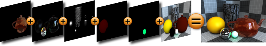
Render output are incredibly useful when users wish to compose the generated layers individually in an external application, such as Photoshop, After Effects, Nuke or Fusion. This can aid in tweaking color, among other settings as a post process without requiring additional render time. The question most often asked is "Which Render Outputs combine to equal the Final Color output?" The answer is "Diffuse Shading (Total) + Transparent Shading + Reflection Shading + Specular Shading + Subsurface Shading + Luminous Shading = Final Color", where each successive layer is added to the layer below in the composition (also called Linear Dodge). Rendering each layer at a gamma of 1.0 and then combining them and adding the gamma back to the fully composed layers will produce the best results.
Users may also render out simultaneous alpha channels for each item in a scene by creating item masks for each and placing a render output set to Effect > Alpha (or simply adding them to existing Shader Tree masks). Then each time a render command is invoked, all active (visible) render outputs will be generated simultaneously.