
MODO provides a few commands to ease the use of sculpting. Found in the 'Utilities' subtab of the default Painting menu.
Geometry to Brush
This is a powerful feature that allows you to convert any selected geometry into a brush for painting and/or sculpting. The command can create height-field (grayscale image) or vector displacement (32-bit color image) brushes from the currently selected geometry. In order for the command to work properly, there must be open edges surrounding the geometry to be converted. Enclosed objects (sometimes referred to as water tight) such as a sphere or torus will produce no results.
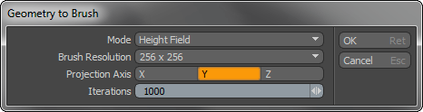
Mode: Users can choose between two options; 'Height Field' creates a grayscale image that is useful for displacing geometry, only taking in to account the actual height of the geometry, ignoring insets and such. The 'Vector Displacement' option is more accurate in capturing the contours of the geometry, accommodating insets and undercuts in the geometry.
Brush Resolution: This option defines the final resolution of the generated image map. Higher resolutions may be necessary to capture finer detail.
Projection Axis: Projection Axis defines the facing direction of the geometry,
Iterations: Higher iterations produce more accurate results, but increasingly take longer to calculate. The default setting of '1000' should be fine in most cases. If you feel the shape isn't being captured properly of the base geometry, you might try increasing the 'Iterations' value.
Relax Mesh
This command uses the same mesh smoothing algorithm leveraged for the Geometry to Brush function. When fired the command requests a number of iterations (default is 5) this will affect the strength of the smoothing performed. This is a very useful command for converting a mesh with detail modeled in to a sculpt-ready mesh. It can also be very useful when creating UV maps for very detailed objects when applied to a Morph map. Users can simply create a morph vertex map, apply the Relax Mesh option to the new Morph, and then UV map the simplified mesh. Once finished, users can delete the additional morph and the UV map will be retained for the original mesh.
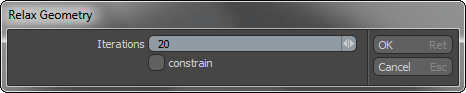
Iterations: This value defines how many times the relax operation is applied to the model. Higher values will produce increasingly smoother geometric surfaces.
Constrain: When the 'Constrain' Option is selected, the relaxed mesh with take into account additional unselected geometry in a mesh item layer. This function gives users an additional degree of control over smoothing, where geometry can be placed inside a mesh, then select the mesh that is to be smoothed, select the Constrain option and apply. The relaxed mesh will conform around the unselected geometry. This function works much like the Background Constrain function, but requires the additional geometry to be in the same mesh layer.
Copy to Morph
This is a convenience command that will quickly copy the current state of your mesh into an 'Absolute Morph' vertex map. This allows you to quickly store the current sculpt state of your mesh which you can restore at any time via the Morph Tool. It is important to note that this is only relevant to the changes made directly to the mesh and is not useful when working with image based or multiresolution sculpting.
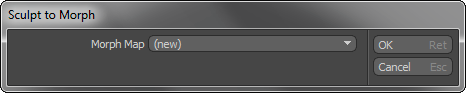
Morph Map: This option allows users to either create a new 'Morph' vertex map, or to store the sculpt information in an existing Morph Map by selecting it from the option list.
Convert to Multiresolution
This command will convert any image based displacement into
Multiresolution sculpting information. This can be displacement derived from both sculpting or standard image based displacement (procedural displacement will need to baked down to an Image Map first). To convert one only needs to make sure the target mesh is selected and then run the command, found in the 'Utilities' subtab of the Sculpting and Painting interface. With the dialog open, select the desired 'Subdivision Level' and press 'OK'.
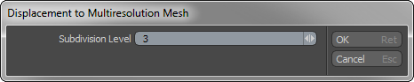
Subdivision Level: This option determines the maximum Multiresolution Subdivision level. You will want to make sure to set the value high enough to capture all the details of the original displacement, but not so high that the mesh becomes unwieldy.

