
When creating high resolution assets using functions such as multi-resolution sculpting, it's easy to create geometry that would be difficult to rig and animate. Too man
y vertices, no attention paid to surface topology. This and other things can lead to odd, unrealistic deformations. The solution for getting a free-form high resolution model into a format where it can be easily animated is to 'retopologize' the model. What this means is to take a high resolution mesh and use that as a base to generate a much lower resolution mesh. The lower resolution mesh can have more thoughtfully placed geometry that is easier to weight and rig. From there a displacement map can be baked resulting in a final asset that is visually the same as the free-form geometry, but a lot lighter, providing better deformations and smoother interactivity when animating.
In order to facilitate the function of retopologizing models, the Topology pen was created to ease users in creating that lower resolution mesh. This combined with the Pen tool and Topology Sketch, set to a Background Point Constraint should be all that users need to completely retopologize any high resolution geometry. MODO also has a dedicated 'Topo' interface tab that is dedicated to the functions of retopologizing models, making all the tools and settings available in a single convenient viewport.
Note: In a past life the Topology Pen was known as the Drag Weld tool. When features were added to increase its usability, it was renamed, but the same functionality is still there.
Using the Tool
Retopology works by first having the high resolution mesh as a background element. This means it is visible in the Items List, but is unselected. Next making sure MODO is in 'Polygons' component mode, and not 'Items' mode, create a new empty mesh layer by pressing the 'N' key. Select the new Mesh layer in the Items List (renaming it if desired). It is best to begin placing some initial geometry using either the Pen Tool; using the Quads mode is especially helpful in laying down strips of quadrangle polygons, or the Topology Sketch Tool that also lays down a series of quadrangle polygons along a drawn curve that conforms to the background surface. Once the basic contours are mapped out, users can activate the Topology Pen tool and begin to extend edges and adjust the geometry into the final surface. The Topology Pen tool, depending on settings offers a broad range of functions, some even duplicating those of other tools, providing a more convenient and fluid workflow.
By default the Topology Pen tool also activates a Background Constraint type of 'Point', ensuring all vertices created will lie directly on the surface of the background mesh. To use, select the tool by pressing the icon in the 'Topo' interface tab's toolbox. This brings up the properties panel where users can select the proper 'Mode' and options, and manipulate the geometry in the 3D viewport. Users can see the geometric element they'll be editing by the pre-highlighting, drawing a ghosted color over the element as the user moves the mouse. LMB+clicking and dragging will apply the defined action, represented by a small yellow box, the distance this box moves is displayed in the 'Offset X/Y/Z' input fields.
There are also some shortcut modifiers that work while the tool is in 'Move' mode--
LMB = Move
RMB = Move Edge Loop
MMB = Split
Shift+LMB = Duplicate
Shift+RMB = Duplicate Loop
Shift MMB = Add Loop
Ctrl+LMB = Slide
Ctrl+MMB = Remove
Smart Snapping
The Topology Pen tool utilizes a custom smart snapping feature that automatically snaps edges together, welding them into a single vertex in the process. The snapping is determined by the proximity of vertices to each other as the user drags the element, snapped edges are indicated by a purple highlight. The welding is not permanent until the mouse button is released meaning users can continue to drag and adjust the position of the element, in turn modifying the snapping, should it incorrectly grab the wrong vertex. Individual vertices can be snapped together as well by simply dragging one vertex onto another.
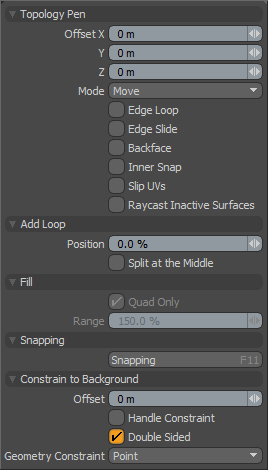 Topology Pen--
Offset X/Y/Z: As users drag in the 3D viewport with the mouse cursor, a small yellow box denotes the point of reference, the distance it travels is displayed in this input field. Once the location is defined by clicking the mouse, users may also manually adjust these input fields directly to manipulate the target component.
Mode: There are a variety of modes, offering functions directly related to the process of retopologizing geometry, all in a single tool-
Move- When an element is LMB+clicked and dragged the element will move but remain fixed against the background surface as it slides around. Useful in editing, vertices, edges and polygons.
Duplicate- Duplicates an edge as the user drags. LMB duplicates a single edge, With the 'Edge Loop' option enabled, or by using the RMB button users can duplicate an entire edge loop simultaneously. Also duplicates individual vertices making triangle polygons.
Remove- Completely removes the element from the geometry, does not modify individual outer edges, but will remove interior edges, vertices and entire polygons. RMB will remove an entire loop.
Split- LMB+clicking and dragging a vertex will create an edge that can then be dragged over and snapped to an adjoining vertex, splitting the geometry with a new edge.
Add Loop- LMB+clicking an edge will create a new edge across the entire span or loop of geometry until another edge or a triangle is encountered. Dragging while the mouse is depressed, will interactively adjust the position of the loop, unless the 'Split at the Middle' option is enabled.
Point- The 'Point' mode draws one point polygon at the mouse down position in any empty area. If any geometry component is clicked in this mode, it then works the same as the 'Move' mode.
Fill- The 'Fill' mode looks for nearby edges and points (vertices) and tries to automatically generate a quad or triangle polygon from them. This mode is useful to fill large areas with a grid of polygons when combined with the 'Point' mode used to place the vertices. Next, switching to 'Fill' mode, simply click in the center of where each quad polygon should appear to create the geometry. Pre-highlighting of the polygon indicates what geometry will be created when clicked.
Edge Loop: When enabled, any adjustments will modify an entire continuous loop of geometry until an opposing edge or triangle is encountered, instead of a single geometric element.
Edge Slide: When enabled, the moving of edges and vertices will be restricted to the positions of adjoining edges, in effect sliding along the edges of neighboring geometry. Pressing down 'Ctrl' while in 'Move' mode provides the same functionality.
Backface: Normally, backward facing polygons are ignored for snapping, when 'Backface' is enabled, users can also snap geometric components against the back side of a surface.
Innersnap: Interior vertices for a surface (those with no open edges) cannot be snapped to other interior faces, snapping only occurs between perimeter vertices. When 'Innersnap' is enabled, any vertex will snap to any other vertex regardless of its location (in the same layer).
Slip UVs: UV values are generally fixed to specific vertices, subsequently further edits to the geometry may warp, deform or otherwise distort the UV values in undesirable ways requiring users to adjust the map or redo it altogether. To avoid this undesirable result, users can enable the 'Slip UVs' function so as to not disturb any existing UV mapping applied to the geometry.
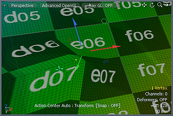 'Slip UVs' function disabled, note texture warping. | 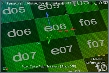 'Slip UVs' function enabled, texture remains even. |
Raycast Inactive Surfaces: When 'Raycast Inactive Surfaces' is enabled user will be unable to select foreground geometry components that are hidden behind the background geometry. This is useful for instance when retopologizing layered elements, such as fingers. When working from a side view, there would be several fingers overlapping in the viewport, making it difficult for the Topology Pen to discern which edge to highlight for duplicating. Enabling this option makes it so that the foreground retopology geometry that is behind the nearest surface, and occluded by the background object (ie the other fingers) would be ignored. Only the retopology surface that is the closest to the viewer would be active. It does slow the tools interactivity though, which is why this option is disabled by default.
Add Loop--
Position: When the mode is set to 'Add Loop', this value determines the position along an edge where the new line of polygon edges will be added, computed as a percentage along each edge encountered. After adding the loop with a LMB+click in the 3D viewport, this input value can be directly modified further adjusting the resulting position.
Split at the Middle: When this option is enabled, new edge loops will be created fixed at the 50% center position.
Fill--
The 'Fill' options are only available when the Topo Pen tool is in the 'Fill' mode.
Quad Only: When the 'Quad Only' option is enabled, the Fill mode option will try to force only four sided quad polygons.
Range: The 'Range' determines the search area around the cursor when looking for vertices to convert to polygons.

