
The Solid Sketch tool provides a quick method for roughing out organic shapes, building up basic geometry with just a few clicks. Users click to place individual nodes that interconnect automatically. The results are something like a subdivided cube that has been automatically extruded or bridged between each node as it is placed. The geometry then becomes the basis for more complex or detailed forms with further editing. Individual nodes can be selected and edited, even after the tool has been dropped.
Usage
The tool is found in the Modeling toolbox, under the 'Basic' subtab as a alternate option of the 'Tube' tool button. RMB to open the popup menu and LMB+click to select it. It can also be activated from the menu bar under "Geometry > Draw > Solid Sketch". When activated, users can LMB+click in the viewport to place nodes. Nodes are always created and positioned relative to the Work Plane. Click and drag will scale the node as it is created. After releasing the mouse and then LMB+clicking and dragging again on an active node, users can adjust the position of it relative to any other nodes that may be present.
Active nodes are indicated by the yellow color of the center dot and always surrounded by the tools handles. These handles allow the user to squash and stretch the node and rotate it. LMB+click over the desired handle dot and drag to apply the action. Previously created nodes can be selected by LMB+clicking over its center dot. RMB+clicking on an the selected node will scale it. Shift+LMB+click and drag will reposition the node and any child nodes further down the chain. New nodes will always connect to the previously selected node. To create an additional branch, select the desired parent node and then draw the new node by LMB+clicking. Individual nodes can be removed by MMB+click.
It should be noted that any mesh created with Solid Sketch will also place a series of two point poly lines inside the mesh so that when the tool is reactivated, it will recover its previous state from the information the poly lines contain. It should be noted that any additional geometry in the layer at that time the tool is re-activated is deleted when re-initializing the tool with this information. When the tool is active, the following attributes are available in the Properties viewport-
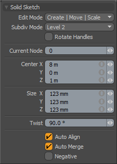 Solid Sketch--
Edit Mode: The default value of "Create|Move|Scale" allows you to create and scale the node on initial click-drag and then use the various handles to control the node further. In this mode you can delete a node by MMB clicking directly on the node. You can also set the Edit Mode to "Destroy" if you want to quickly click on several nodes to remove them.
Subdiv Mode: This setting determines how many tessellation levels to apply to the mesh using the SDS algorithm. Setting this value to 0 reveals the raw polygonal cage. Increasing the value to two will create additional edge loops at each node. This can be particularly useful when creating complex branching from a single node as it produces smoother results.
Rotate: When this option is enabled the rotate handles are drawn as Red, Green and Blue rings around the selected node. These represent rotation around the Z, Y and X axes respectively. To rotate the node simply click and drag on the desired ring handle. The affect of using the rotation handles is to actually move the children nodes of the current node as if the selected node were being reoriented.
Current Node: Nodes are internally numbered in the order they are created, the current selection will always be reflected in this field, users can change the value to select a different node manually.
Center X/Y/Z: These values define the position of the selected node. LMB+clicking and dragging in the 3D viewport will adjust the position interactively, or users can adjust these value manually for finer control.
Size X/Y/Z: These values define the basic size of the selected node. RMB+clicking and dragging on a selected node in the 3D viewport will adjust the size interactively, or users can adjust these value manually for finer control.
Twist: The protruding side handle on the selected node allows users to apply a simple twisting effect to the node interactively. This value can be manually adjusted here for finer control. Twisting the node will not affect the position of the nodes connected to it.
Auto Align: With this option enabled each node reorients the geometry it creates to more smoothly blend with the surrounding geometry segments.
Auto Merge: Since each node typically generates a cube of polygons around it, bunching up nodes close together would cause the mesh to pinch. The Auto Merge setting will reduce a nodes created geometry by merging it into other nodes once they are too close together.
Negative: Off by default, this option causes a node to repel neighboring geometry. This can be useful to create divots in the mesh.

