
The Curve Extrude tool allows users to quickly extrude a geometry selection along the length of a curve. If the curve is pre-existing, select it first, then the polygonal geometry for extrusion. 'Curve Path' will also allow the user to create a path interactively. To use, select the tool and make it interactive by clicking in the viewport. Once activated, a number of properties are available
 PathSteps Generator--
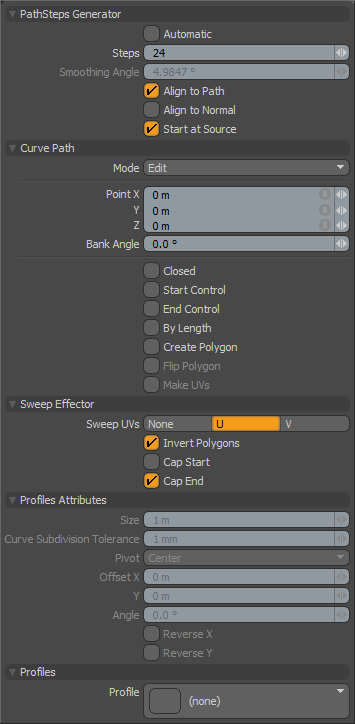
Automatic: This toggle control will force a computed number of clones based on the Smoothing Angle value such that a clone is placed along the path to maintain a level of smoothness at or above the user set level (determined by the 'Smoothing Angle').
Steps: The 'Steps' option is active only when the 'Automatic' option is disabled. The defined 'Steps' value determines the number of particles generated along the curve path that feed into the Effector, essentially controlling the number of segments of the resulting extrusion.
Smoothing Angle: Determines the angle along the curve where a clone will be created when the 'Automatic' option is enabled.
Align to Path: When enabled the generated particles will include rotation information so the newly created clone aligns to the path vector direction at the location where it is created.
Align to Normal: When enabled, the generated particles will include rotation information so the newly created clone aligns with any stored normal direction for a vertex, such as for a curve extracted from geometry.
Start at Source: Often a curve used for cloning will have its initial control knot imperfectly aligned with the geometry to be cloned. With Start at Source active the curve is used as a relative guide using the original geometry as the true starting location. Disabling this option may cause the newly created geometry to move away from the intended original location.
Curve Path--
Mode: By default the mode is set to Add. In the 'Add' mode clicking on a curve point and dragging will edit the curves position. Clicking anywhere in the 3D viewport other than the handles will create a new curve control point. To avoid creating new control points when dragging existing points around you can set this mode to 'Edit'. 'Delete' mode allows quick removal of control points by simply clicking on them.
Point X/Y/Z: The XYZ position of the currently selected knot. The user can interactively edit the position by clicking over the knot indicated by the cyan dot, it will turn yellow; the user can now drag its position around in the viewport, or manually enter a position by editing any of the data fields.
Bank Angle: For each path position, a bank angle can be defined that controls the rotation angle of elements cloned through that position.
Closed: This toggle option will cause the curve to become a closed loop, connecting the end point to the start.
Start Control: Enabling this toggle will cause the first knot in the curve to become a control point but not an actual segment of the curve. This provides a simple method for changing the curvature at the start of the curve.
End Control: Enabling this toggle will cause the last knot in the curve to become a control point but not an actual segment of the curve. This provides a simple method for changing the curvature at the end of the curve.
By Length: This option forces the newly created geometry to be evenly distributed across the entire length of the curve rather than spacing based on the control knots.
Create Polygon: This toggle option will generate a curve type polygon that remains after the tool has been dropped. This is useful if you want to re-use the curve you create with the current tool with additional curve based tools later in your project.
Flip Polygon: This toggle will invert the faces of the generated polygons.
Make UVs: When this toggle is active the tool will populate the current UV map with data for the generated polygons.
Sweep Effector--
Sweep UVs: This popup control allows you to choose between the U or V axis when placing UV data for newly created geometry.
Invert Polygons: Reverses the normal facing direction of the polygons generated by the extrusion. Useful when extruded geometry appears inverted or inside-out.
Cap Start/End: This toggle will force the back end of the extruded geometry to be capped or closed.
Profile Attributes--
Size: The size of 1D or 2D profile to sweep. If the size is 0.0, it uses the real size.
Curve Subdivision Tolerance: This is the minimum angle when it subdivides the bezier curve to a string of two-point polygons for extrusion. This setting basically controls the detail tolerance of the conversion from the original curve to the resulting polygon extrusion.
Pivot: Specify the pivot position of the profile.
Offset X/Y: These are the offset amount on the profile space.
Reverse X/Y: Reverse the selected profile to horizontal or vertical.
Profiles--
Mini Preset browser for viewing various profiles. Works the same as the standard preset browser. Selecting any of the various profiles will modulate the extrusion width with the selected shape over its length. To return to the original polygon selection for the extrusion, ctrl-click the selected profile to deselect it.

