
The Bridge tool will create polygons to span the area between selected edges or polygons. There are several options for the Bridge tool that control the way the span polygons are generated, connecting the two locations.
Usage
The Bridge tool is found in the 'Duplicate' subtab of the default modeling toolbox. It can also be found in the 'Edge' and 'Polygon' subtabs (located there for convenience) and can be activated in the menu bar under "Geometry > Duplicate > Bridge". The tool requires a specific selection prior to activating the tool, as a minimum of two polygons that do not share any edges are necessary for the tool to work. The basic principle is that the first polygon, or cluster (group) of polygons selected will connect with the second polygon, or cluster of polygons. Making sure each cluster does not share any edges with the first selection is necessary for MODO to know how it will bridge from the one location to the next. (Note: Edge selections can be used as well, as long as they don't share any vertices between the two or more selections)
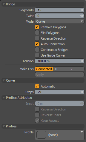
Once the selection is defined, LMB+clicking the tools button will activate the Bridge tool. Clicking again in the 3D viewport will enable the interactive mode, where LMB+clicking and dragging will interactively adjust the number of segments between the polygon clusters. Additional options can be toggled in the tools properties panel as well as the Bridge mode can be set and a Profile can be selected that modulates the shape of the bridge. When the tool is active, the following attributes are available in the tool properties panel-
 Bridge--
Segments: The segments option allows the user to determine the number of polygons that are created across the length of the bridge. This value can be set interactively by LMB+click and dragging in the 3D viewport while the tool is active, or numerically on the tool properties panel. For curved Bridge spans or those modulated by a Profile, having more segments will produce smoother results.
Twist: The twist value is used when bridging polygon selections. When the value is set to a non-zero number it will rotate the bridge polygons between the original connection points. This is very useful in cleaning up bridges between disparate polygon selections where the bridge can become overlapped. In that case using the Twist value will often allow you to "untangle" the bridge manually.
Mode (Linear, Curve, Smooth): This popup provides a simple method for setting the interpolation style of the generated bridge polygons. 'Linear' will create a bridge in a straight line between the original selection. 'Curve' will create an arc between the original selection points. 'Smooth' creates an "ease in/ease out" blend between the original selection sections. The 'Curve' option can be further refined adjusting the 'Tension' setting.
Remove Polygons: If polygons were selected prior to activating the tool, this option will remove the originally selected polygons used to create the bridge. This is enabled by default and is the most often preferred behavior.
Flip Polygons: When enabled this option will flip the normals of the newly created polygons in the bridge, such as when a negative Bridge action cause the resulting polygons to appear inside-out.
Reverse Direction: When enabled, MODO will reverse the normal direction of the target polygon cluster when bridging. This can be helpful to resolve a skewed Bridge span that couldn't be resolved by adjusting 'Twist' (un-twisting) alone.
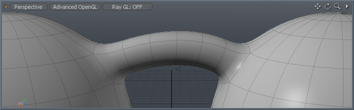
Auto Connection: When 'Auto Connection' is enabled, the Bridge action will automatically add 'Segments' and connect them to adjoining boundary edges when Bridging opposing edges within the same surface all while attempting to retain the surrounding curvature. The sample below shows the edge selection prior to activating the tool, and then the tool activated on the selection bridging between the two clusters and finally the 'Auto Connection' option enabled, where additional spans are automatically added and connected to the border edges.
Continuous Bridge: The 'Continuous Bridge' option when enabled will bridge successive clusters of polygons or edges into a continuous length or tube with the spans evenly divided between each individual span. Selection order is important as it will determine the order in which the spans are bridged.
Use Guide Curve: When using Bridge to connect consecutive curves created with the 'Contour' tool, twisting may occur in the resulting geometry. Users can select a single vertex from each curve in order, and press 'P' to create an open curve. This curve can serve as a 'Guide Curve' and determines a single continuous edge along the final bridged span which will often eliminate the twisting issue. Users will need to create the guide curve and select it prior to activating the tool. Once activated, enable the 'Use Guide Curve' option to use.
Tension: This percentage value provides some additional control over the bridge path used when the Curve mode is active. Increasing this value will accentuate the curved effect and decreasing it will mute the effect toward the linear path.
Make UVs: Determines how a UV map is automatically generated for the resulting geometry
Connected- Simply connects the edges between existing UV values as a straight line.
U/V- Fills the entire UV map 1-0 area with the resulting bridged geometry in the specified orientation.
Curve--
It is possible to Bridge between selections of two curves, and by enabling the 'Continuous Bridge' option, a series of successive curves. The smoothness of the Bridging in these cases is controlled by the 'Segments' between spans, and the 'Steps' value across the curve. The 'Tension' setting will control how smoothly one span blends into the next.
Automatic: This option, when enabled, will automatically determine the 'Steps' value subdividing the curve based on the mesh item layers 'Curve Refinement Angle' setting.
Steps: When the 'Automatic' option is disabled, the 'Steps' value determines the the number of curve subdivisions. Larger values will produce smoother surfaces, while smaller values will produce more faceted surfaces.
Profile Attributes--
Inset: Specifies the X direction offset amount of 1D profile.
Reverse Direction: If this option is enabled, the 1D profile is evaluated from top to bottom.
Reverse Inset: If this option is enabled, "Inset" will be reversed essentially mirroring the profile.
Keep Aspect: Automatically sets the "Inset" value based on the aspect ratio of the profile.
Profiles--
Mini Preset browser for viewing various profiles. Works the same as the standard preset browser.

