
The Boolean command allows the user to combine mesh layers in various ways (Union, Intersect, Subtract and Add). By doing so, more complex shapes can be created that would otherwise be difficult to create manually.
Usage
Any mesh that is to be used for a Boolean operation will need to fulfill some specific criteria in order to work properly; meshes must not have coincidental overlapping (non-manifold) geometry (vertices, edges or faces that share the same position in space), nor are any floating vertices allowed. It might be useful to run the 'Mesh Cleanup' script prior to attempt a Boolean operation to ensure a clean error-free mesh. Additionally, both the driver and driven mesh must have some volume and must be water-tight (meaning if the geometry were a filled solid, nothing could leak from it --i.e. no open edges). Once the geometry is prepared for the boolean operation, then the driven mesh will need to be in the foreground and the driver mesh in the background (unless specified differently). This is determined by the Items list, layers that are selected and visible (denoted in the list by their highlighting) are the foreground layers, and layers that are visible but not highlighted are the background layers. For information on working with layers in the Items list, please reference that page of the documentation. It may be helpful (and speed up the procedure) to disable any unnecessary background layers (by dragging over the eye column of the Items list).
Once the Geometry is set and foreground and background are assigned, the boolean command can be invoked. It can be found in the 'Mesh Edit' subtab of the default modeling toolbox. LMB+clicking the command button will open the following dialogue box, Users can select the desired 'Operation' and press 'OK' to perform the Boolean.
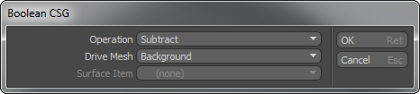
Operation: The 'Operation' determines how the different layers are treated-
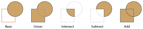
The 'Base' illustration above shows the square shape as being the background element and the circle in the foreground. The different operations are then demonstrated showing their results.
Union: Combines the two layers together as a seamless mesh removing any overlapping geometry.
Intersect: Results in a mesh created only in areas where the two layers are overlapping. All sections of the two layers that are not overlapping are removed.
Subtract: Removes the background layer from the foreground layer, cutting away any section of the foreground that overlaps with the background layer. New faces will be created to close the area where the background layer cuts through the foreground.
Add: The geometry from both layers are combined into a single mesh. No geometry is removed, but extra vertices are created to ensure the meshes are stitched together.
Drive Mesh: This option allows the user to determine what mesh will have an affect over the boolean operation. By default, it is the 'Background' option that controls the Driven mesh, defined by the items Background/Foreground designation in the Items list. 'Last Selected' will use whatever geometry is selected when the Boolean operation is invoked. This allows Boolean operations to be applied within a single mesh item layer. 'Specific Surface Item' allows the users to designate a specific mesh layer (including 'Groups' of multiple items defined in the Groups palette) to act upon the current active layer.
Surface Item: When the 'Drive Mesh' option is set as 'Specific Surface Item' this option allows users to determine which mesh item layer can be used to drive the Boolean operation. Groups will always need to be selected here.

TIP: The results produced by Boolean operations are not generally compatible with subdivision surfaces. Depending on the shapes and how they overlapped, the resulting boolean may produce oddly shaped polygons with greater than four edges, that tend pinch and pucker. Most often some amount of manual clean-up is required to generate results that a useful to a subdivision surfaces model (a discussion beyond the scope of this documentation). If you wish to simply produce rounded edge at the intersection, you might try applying the 'Edge Bevel' tool to the new edges that result from the Boolean (if the original geometry was simple enough) or better visual results could be obtained more simply by applying the 'Rounded Edges' function of the Material Item. See also 'Drill' and 'Solid Drill'. These commands allow you to perform similarly related boolean operations without the merging of the geometry.

