
The Bezier Extrude tool allows one to quickly extrude a geometry selection along the length of a bezier curve. The path can be pre-generated, or with the tool active, can be drawn and edited interactively while cloning the target element(s). A Bezier Curve is a type of curve defined by additional off-curve control handles providing users an intuitive means to control the amount of incoming and outgoing curvature for each control point.
Usage
The 'Bezier Extrude' tool is found in the 'Duplicate' subtab of the default modeling toolbox. One may have to RMB+click to open the button popup menu to find it (by default it is located under the 'Curve Extrude' tool button). Alternately, the tool is also found in the menu bar under "Geometry > Duplicate > Bezier Extrude". LMB+click the button to activate the tool. Next, in the 3D viewport, click to position the first control point and then continue to drag the mouse cursor to create the bezier handle. Releasing the mouse button will set the handle length. Subsequent clicking and dragging will draw additional control points and handles with a curve segment drawn between each vertex. The extruded geometry will interactively display across each new segment as it is drawn.
When drawing out the Bezier for extruding, control points will always be created at the intersection of the Work Plane and the mouse button click. The curvature of the segments between control points is defined by the bezier handles (called 'endpoint tangent vectors'). While the tool is active, users can hover over any of the control points (changing them from blue to yellow) and LMB click and drag to reposition it. Points will always move on the two axes relative to the current Work Plane, so rotating the viewport to change an axis may be necessary. Handles are edited in the same manner. Pressing and holding the 'Ctrl' key when editing handles will break tangency allowing opposing handles to be different lengths and/or angles, editing any handle without pressing 'Ctrl' will restore tangency. When editing (moving) control points, pressing and holding 'Shift' will move all downstream control points as a single unit.
There are three Bezier editing modes, allowing users to 'Add' any additional control point after the most recent selected control point, 'Edit' allows users to change a control points location and 'Delete' removes any control point that is clicked. Control points along the Bezier Curve can also be positioned precisely during editing by selecting the target vertex and using the Point X/Y/Z fields of the tools properties panel. Once the tool is dropped by pressing the 'Q' key, the cloned items will be in effect set and no further editing of the path is possible. However, using a pre-drawn path will allow the user to delete the resulting extrusion and re-create it with modified settings.
Pre-drawn Path
To use a pre-drawn bezier path for extrusion, one will need to make sure the path itself is selected prior to activating the tool, this is done while in the 'Polygons' selection mode. With the target curve selected, activate the tool (by clicking the tools button) and then again clicking in the 3D viewport, this triggers the cloning of the selected element along the bezier. If desired, the bezier can then be edited in the same manner as if it were drawn with the tool.
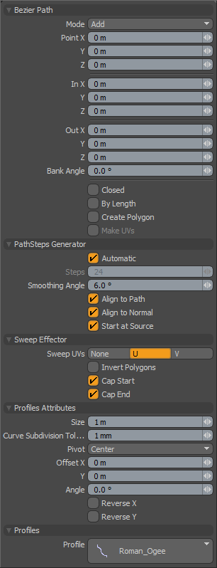 Bezier Path--
Mode: The various bezier curve mode options available are--
Add-- The default mode, when users click in the viewport, additional points are added to the curve. At each control point position two handles extend out that allow users to adjust the curvature of the curve segment between vertices. While drawing users can hover over any point or handle where it will turn yellow, users can then LMB+click and drag the control point or handle to further edit the curve. Control points may be added mid-curve by selecting the preceding control, highlighting it yellow, and clicking the position where the new control point is desired (point order is defined by the initial order in which the curve was created, press the 'F' key prior to activating the tool will invert the order).
Edit-- In edit mode users can freely LMB+click drag and of the control points or handles along the curve to change the look to the desired shape. While pressing the 'Ctrl' key, users may break the tangency of the control handles, allowing for sharp corners.
Delete-- In delete mode, users can LMB+click on any control point along the curve to remove it from the bezier.
Point X/Y/Z: Users wishing finer point control can assign specific XYZ values in these input fields for the currently selected (highlighted) control point.
Bank Angle: The orientation of the extruded geometry is determined by the orientation of the initial polygon, and the 'Align' options, if enabled. The 'Bank Angle' option provides users an additional control, per path vertex, for banking or angling the extrusion from side to side. Bank value will then smoothly blend with the values of the previous and later control point positions.
In X/Y/Z/Out X/Y/Z: Users wishing finer handle control can assign specific XYZ values in these 'In' and 'Out' input fields for the currently selected (highlighted) control point.
Closed: The 'Closed' toggle option adds an automatic curve segment between the first and last control point positions producing a closed extrusion.
By Length: When the 'By Length' option is enabled, segments of the extrusion will be evenly distributed along the path by equal lengths rather than by the span (space between control points), which may produce uneven segments.
Create Polygon: When the 'Create Polygon' option is enabled, dropping the tool will leave the Bezier Curve path instead of removing it from the scene. This is useful should the user wish to use the resulting curve for additional purposes.
Make UVs: If the 'Create Polygon' option is enabled, this toggle activates auto-generation of UV texture coordinates along the curve. The generated UV values will be of a single vertical line ('V' axis in UV) positioning all the control point vertices evenly between 0 and 1. For example, this can be useful for applying a Gradient to a rendered curve (the 'Render Curves' option is available in the 'Mesh' Items properties.
Path Steps Generator--
Automatic: When the 'Automatic' option is enabled, MODO will assign the number of segments to the path based on the number of control points combined with the 'Smoothing Angle' option. This method will bunch-up the most segments around the curvy areas, and produce fewer segments on the straight areas of the curve, which may be desirable. For even spacing of segments, enable the 'By Length' option above and disable 'Automatic'.
Steps: Available only when 'Automatic' is disabled, this option allows users to specify an exact number of segments along the path.
Smoothing Angle: When the 'Automatic' toggle is enabled, the 'Smoothing Angle' will determine the distribution of the segments along the curve. Smaller values will produce more segments, and larger values will reduce the number of segments. The 'Smoothing Angle' basically defines what the difference between two positions along the curve is, if the next positions falls within the 'Smoothing Angle' threshold, a new segment is generated.
Align to Path: This option when enabled, changes the orientation of the segments along the curve. The first segment will retain its original orientation and subsequent segments will be angled away from the first based on the changing (vector) angle of the bezier curve.
Align to Normal: When this option is enabled, MODO will try to align the direction of the source objects to a straight up position before cloning the source item(s). If the item is already upright when cloned, this option will likely have no effect.
Start at Source: By default, MODO will clone items at the actual world position along the bezier curve. When the 'Start at Source' option is enabled, MODO will offset each cloned item the distance between the source items center point and the first curve point,producing an effect as if the curve were initiated precisely at the center of the first source item.
Sweep Effector--
Sweep UVs: This popup control allows the user to choose between the U or V axis when placing auto-generated UV values for the newly created geometry.
Invert Polygons: Reverses the normal facing direction of the polygons generated by the extrusion, useful for when the extrusion travels along a negative axis causing inside-out geometry..
Cap Start/End: This toggle will force the back end of the extruded geometry to be capped or closed.
Profile Attributes--
Users can select a profile for extrusion prior to activating the tool by pressing 'F6' and selecting from one of the available profiles (default content must be installed)
Size: The size of 1D or 2D profile to sweep. If the size is 0.0, it uses the real size of the original profile.
Curve Subdivision Tolerance: This is the minimum angle when it subdivides the bezier curve to a string of two-point polygons for extrusion. This setting basically controls the detail tolerance of the conversion from the original curve to the resulting polygon extrusion.
Pivot: Allows the user to specify the pivot position of the profile.
Offset X/Y: Allows the users a way to 2-D offset the profile relative to its 'Pivot' location.
Reverse X/Y: Reverse the selected profile to horizontal or vertical.
Profiles--
Mini Preset browser for viewing various profiles. Works the same as the standard preset browser. Selecting any of the various profiles will ignore any selected or active geometry in the scene and extrude the Profile instead. To return to the original polygon selection for the extrusion, 'Ctrl'+click the selected profile to deselect it.

