
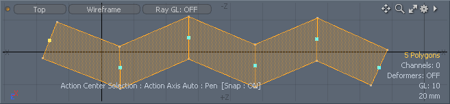
The Pen tool allows users to create geometry vertex by vertex by clicking in the 3D viewport. One can use the Pen tool to create Polygons (default), lines, vertices, spline patches or subdivision surface polygons.
Usage
The Pen tool is found in several locations within the default interface. It can be found under the Basics subtab of the modeling toolbox as well as the Polygon subtab. It is also found in the 'Topo' tab toolbox. LMB+clicking the tools icon will activate the tool. Next, clicking in the 3D viewport will set the Pen tool in to interactive mode. Depending on the 'Type' option selection, slightly different components will draw in the interface. When the tool is active, users can also click directly on any of the vertices it has created in the current session and drag them in 3D space for direct editing, they'll turn yellow when the mouse is directly over them. Clicking away from a vertex will create a new vertex in that location. To start a new line without dropping the tool, press shift LMB+click. Clicking on previous vertices made within the same tool session will weld the new vertex/line section together. To insert a vertex, highlight a previously created one, and click away from it and the new vertex will be inserted after the selected vertex. When creating Quad Strips with the 'Make Quads' option enabled, an occasional triangle can be created by pressing the 'Ctrl' key. When the tool is active, the following options are available in the tools properties panel-
 Pen--
Pen--
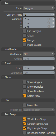
Type: This pop-up button allows you to select between different modes-
Polygons-- In Polygon mode, users can draw individual polygons vertex by vertex. The first click of the mouse creates a new vertex and each subsequent click will continue adding vertices to the active polygon. Pressing 'Shift' will start a new polygon.
Lines-- The Line type will create two vertex polygon line segments (polyline).
Vertices-- The Vertices mode will simply create new vertices with each click leaving you with a vertex (point) cloud.
Spline patches-- Spline patch mode acts exactly like Polygon mode but creates polygons of type Spline Patch.
Subdivision Surfaces-- When using 'Subdiv' mode the pen tool simply creates polygons tagged as SDS.
Current Point: You can change this setting to change the current vertex to be edited by the numeric values listed as Position X, Y, Z. Since the tool may have created several vertices, it is useful to be able to choose one numerically. The vertices are numbered in sequence as they are generated by the tool. Clicking on any vertex in the 3D viewport (from the current Pen tool session) will also display its numeric value in the sequence.
Position X/Y/Z: This numeric entry field allows you to precisely edit each vertex created by the tool. Simply set the Current Point value to the vertex you wish to edit and enter the numeric values for the X, Y and Z positions. Clicking any vertex in the 3D viewport will also display its current position.
Flip Polygon: This option will simply invert the surface normal of the polygon(s) created.
Close: The 'Close' toggle will automatically draw a line between the first and last vertex created making a closed loop.
Merge: The 'Merge' function will automatically 'Merge' or combine vertexes within close proximity to each other when created.
Make Quads: This option will automatically place vertices to create quads with each new click after the first two vertices have been set. This mode makes it very simple to create polygon strips. Pressing the 'Ctrl' key will create a single triangle. Option is only compatible with the 'Type' > 'Polygons' setting.
Wall Mode--
Wall Mode: With mode type set to 'Polygons', Wall mode will allows the user to draw out polygon strips that look like a building floor plan. effectively creating the foundation for rooms. There are 4 settings, 'Off', disables wall mode, 'Inner' will draw the wall segment on the inside of the polyline, 'Outer' will draw the wall segments on the outside of the polyline, 'Both' will extend the wall segments on both sides of the polyline. Once the tool is dropped, the resulting wall mode polygons can be 'Thickened' into upstanding walls.
Offset: The Offset value represents the thickness of the wall, when in wall mode. Note then when wall mode is set to both, that offset will be doubled. This value can also be set interactively with the RMB+click in the viewport, much like adjusting brush size for painting.
Inset--
Inset: When 'Wall Mode' is enabled, this option allows each new vertex to be beveled into multiple segments for quickly flattening or rounding corners.
Segments: Only available when Inset is non-zero this value determines how many vertices to create in order to facilitate the inset value. Increasing this value makes more complex and rounded corners. Using a value of one results in flattened corners.
Show--
Show Angles: Toggles the display of corner angles between opposing edges in degrees, drawn in ghosted form over active geometry.
Show Handles: Toggles the display of tool handles offering users the ability to adjust the previously created vertex by axis.
Show Numbers: Toggles display of the vertex point order values in the viewport.
Select New: Toggles the selection state of the most recently created polygon while the tool is still active.
UVs--
Make UVs: When enabled this setting will automatically make UVs for the created geometry further defined by the 'Project To' setting.
Project To: Determines the way that the UV map is created
Action Axis-- With this setting, the Pen tool determines the UV map projection axis based on the current Work Plane for the created polygon. UVs are created in space relative to where they are drawn in 3D space, so only points drawn with the 0m to 1m world space will appear within the 0-1 UV space.
Backdrop Item-- Useful for drawing polygons over a Backdrop item, the UVs are projected onto the backdrop item to match position. So, for instance, if you created a polygon over the tire of car backdrop image, the new polygon would inherit the UV position of the tires location in the image relative to UV space.
U/V Direction-- When in 'Wall Mode', this setting will automatically generate a row of regular quad UV coordinates for the polygons along either the U direction (horizontal) or V direction (vertical) as specified.
Pan Snap--
World Axis Snap: When this is active the pen tool handles will snap along the world XYZ axis once you have created more than one vertex.
Straight Line Snap: Will try to snap the handle to a position that will create a straight line between the next and previous vertices in the polygon being created.
Right Angle Snap: Will effect a snap when the angle created by the current, previous and next vertices create a 90 degree angle.
Raycast Handle Position: With this option enabled, vertices behind the background mesh will be unselectable. What this means is that vertices hidden behind backwards facing polygons will be ignored for snapping and editing.

