
Modeling in 3D is most often the act of creating and modifying; users typically start with a basic shape and then utilize the transform or deform tools to shape the geometry into the intended form. In order to introduce new users to modo, we're including a simple step-by-step tutorial walk through for modeling and rendering a coffee mug; simple enough to go through the various steps in detail so users can better understand modo's powerful tool set and unique workflow. It is expected that users are comfortable using a mouse, clicking and dragging, can navigate menus and have a basic familiarity with modo's interface. If not, it is recommended users read up on the 701 interface page of the documentation to get an idea where the various panels are located. It may also be extremely helpful for users to go over the User Interface Conventions page for a better idea on how users are expected to interact with modo. Along the way, I'll be explaining essential concepts as they become important. If you've already covered modeling the mug, you may wish to skip to the Rendering part of the tutorial.
Getting Started
Before we begin, lets make sure we're looking at the same window. modo, by default, offers multiple interfaces or layouts by way of the tabs directly under the menu bar (referred to in these docs as the interface tabs), each with a focused toolset targeted toward the particular task. If you're not seeing any tabs, you may have switched out of the Tabs layout and into one of the Layout workspaces. These layouts can be selected directly in the menu bar under "Layout > Layout", or by using the faster keyboard shortcut to swap interfaces. This is done by pressing the 'Ctrl' key and then the 'Tab' key at the same time opening the 'Layout Switcher' where you can subsequently press the 'Tab' key multiple times (while still holding down the 'Ctrl' key) to toggle through all the layouts (or LMB+click on the Layout icon to directly select one).
Modeling is best accomplished, not surprisingly, using the 'Model' interface. We'll be working in the 'Model' tab (or 'Layout') of the default interface which provides a large Perspective view of the so far empty scene. You'll also want to start with a new empty scene, so if you haven't just started modo, press 'Ctrl+N' to create a new blank scene. Now onto the mug, the best way to start a project is to know what it is you want to do, and that means gathering reference. Here's an image of the coffee mug we'll be modeling.

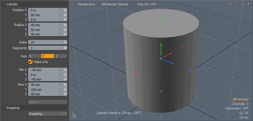
It will be easier to tackle the main body of the mug first, then add the handle later. As mentioned above, modeling is often the act of creating and then modifying, so that is exactly what we're going to do here. First let's examine the shape of the mug. It could be considered somewhat cone-shaped, but it would probably be easier in this case to define a cylinder shape and modify that. So lets do that. LMB+click on the 'Cylinder' tool icon to select it, it's located in the 'Basic' sub-tab of the toolbox, located on the left side of the interface. When selected, its background will change to an orange color and its attributes will appear in the 'tool properties' viewport directly below the toolbox (pictured in the left panels further below).
Cylinder tool icon
You'll be using the mouse to create the cylinder in the 3D viewport view, but before you begin to draw you need to make sure the initial drawing orientation is correct. The default 3D viewport has two grids that users can use for reference, the dark grid is stationary and effectively represents the ground plane, within this grid are two darker lines that intersect at the world origin, the 0,0,0 position. The second light colored grid is called the 'Work Plane', this is the more important grid for modeling. It represents where actions occur in 3D space, when the user clicks in the viewport, the action originates at the intersection of the mouse click position and the Work Plane. The Work Plane also determines the orientation. As users spin and navigate in the viewport (hold down the 'Alt' key and LMB+click and drag in the viewport to tumble the view) you can see the Work Plane changes orientation to face one of the three axes. If you tumble the viewport so that the vantage point is facing downward toward the ground plane grid, the Work Plane will align itself to the ground, and set the initial orientation for our cylinder.
Once the Work Plane is positioned properly, hold down the 'Ctrl' key on the keyboard (to constrain all three axes of the cylinder tool to the same value when drawing) and then LMB+click at the origin position and drag outward. This action does two things, first it obviously places the geometry into the scene, the less obvious action is the tool is now in interactive mode; basically meaning that while the tool is still active users can use any of the available handles to modify the cylinder, as well as edit property values and see the shape update in real-time in the viewport. Handles are the controls that allow users to make specific modifications. Once a tool is inactive (referred to as dropped) interactive editing will no longer be possible, so you want to keep your tool in the active state until you have the shape the way you want it.
Let's go over the interactive handles, at the center of the cylinder are three arrows, for moving the position of cylinder, colored to correspond to the axis they move on, then there are small plus or star shaped handles for adjusting radius values individually. Holding the 'Ctrl' key when adjusting any of the handles will again constrain all values to be the same. Nearly all tools will have some type of handle specific to the function it provides.
As an additional note, you may also want to pay particular attention to the orientation of these axes when modeling, as it will allow you to better follow the tutorial when a specific axis is referenced. You can easily follow my orientation by matching the axis widget in the lower right corner of the 3D viewport.
The measurements of the mug are 90mm wide by 100mm tall. Since the Cylinder is defined as a 'Radius' (half the diameter), the size we need is 45mmx50mm, adjust the handles or set the values into the input fields of the properties panel to match those above, LMB+click the red arrow handle and move the cylinder upward so it is resting on the ground, keeping particular note of the 'Min' setting which, in this case, the 'Y' value determines the lowest edge of the cylinder. The above value is at '0' ensuring that the mug will be resting on the ground when rendered. Additionally, the default tool will have multiple edge loops vertically, called 'Segments', in order for this tutorial to work properly, you'll want to set the 'Segments value in the tool properties panel from the default value to '1'. Once you have the values the way you like, press the 'Q' key to drop the tool.

TIP: While the Work Plane was instrumental in determining the first action of the Cylinder tool, it was not a necessity to adjust the handles and make further edits while the tool was interactive. Users can freely tumble and zoom viewports, even when tools are active, subsequent movement of the Work Plane will not adversely affect the geometry.
Editing the Form
For most editing that is applied to the model, you will not want it to apply to the entire mesh equally, therefore you need to tell modo what part it is you wish to edit. This is done through the application of a selection. modo offers several selection modes, these determine what type of geometric selections can be made, either Vertex, Edge or Polygon. If you are not familiar with what these components are, please read through the 'What is 3D' page of the documentation for an overview. modo references the current mode in the 'Modes' toolbar above the main 3D viewport. Users can easily toggle between these modes by pressing the 'Spacebar' to continuously cycle through the three main modes for modeling geometry. To make the next edit, we want to select some Edges, so press the Spacebar until the 'Edges' button is highlighted.
![]()
Now to make the selection. We want to select the entire bottom edge of the cylinder, modo has shortcuts to simplify these kinds of actions. In this case we need to only make a single initial selection. By default, modo makes what are called paint based selections, meaning when users LMB+click and drag over their geometry, modo will select all elements that are brushed over (sort of like painting). LMB+click and drag over one of the lower edges of the cylinder being careful to avoid the upright edges. The selected element will change to an orange color indicating its selected state. Next, press the 'L' key on the keyboard to select all the connected edges in the loop, this is called a loop selection, and is a handy way to edit continuous sections of elements.
With the selection set, we can now make the actual edit. Activate the 'Scale' tool, this can be done by pressing the icon in the interface, but being such a commonly used function, it has a keyboard shortcut 'R'. Press that key and the Scale tool handles should appear in the center of the selected ring of edges shown below here.
We want to scale the loop to 70%. To do that we could click on the ends of the red and blue handles separately setting both to 70% independently (as seen in the properties viewport above), but to simplify this operation the scale tool has an extra handle in the way of the floating circle. By LMB+clicking and dragging on the green circle, users can scale both the 'X' and 'Z' values simultaneously. Once that is applied, again press the 'Q' key to drop the scale tool and return to selection mode. The selection is no longer necessary either, that can be dropped by next pressing the 'Esc' key.
To make the interior of the mug, we'll need to again select some geometry and then edit it. In this case, we need to select the top polygon, so press the 'Spacebar' until the 'Polygons' selection mode is highlighted (like the 'Edges' mode was earlier). In order to know what particular element is being selected, modo has a function called pre-highlighting; when the mouse hovers over a particular element, its color will change indicating it is a selectable element. In this case, hover the mouse over the upper round polygon and simply LMB+click to select. The 'Polygon Bevel' tool is found in the 'Polygons' subtab of the toolbox. It can also be accessed from the 'Shift+B' keyboard shortcut. With the tool active, LMB+click in the 3D viewport to again enter interactive mode for the tool. The bevel tool has two handles, one to offset the polygon, and another to scale, we're simply going to scale the polygon (drawing the additional edges that will become the top of the mug), so LMB+drag over the red handle until the 'Inset' values read 5mm.
Next, it is necessary to bevel the same polygon again, but further editing of the handles will simply modify the initial bevel unless the tool is dropped and reactivated. Luckily, modo is designed to save steps, while the tool is still active, users can hold the 'Shift' key down and LMB+click anywhere in the 3D viewport (away from any tool handles) and reset the bevel tool allowing an additional application of another bevel without the need to drop and reactivate the tool. This time LMB+click and drag the blue handle down to a value of '-95mm'. Press 'Q' now to drop the tool. Activate the 'Scale' tool again (by pressing 'R') and again scale the selection to 70%, just as before. (You might be wondering why the inset of the bevel wasn't used and instead replaced with a 'Scale'. Since the Bevel specifies the inset as a measurement, it was easier to keep the inside consistent to the outer rim by giving it the same scale value).
Indirect Selections
The mug in the photo has nice rounded edges, unlike this model so far, so we need to round them using the 'Edge Bevel' function. Since we only want to affect certain edges, we'll need to make a selection, but it will actually be a little difficult to get inside the cup to accurately select the edges necessary, so modo has way to indirectly make the selection we want. (Making sure you're still in 'Polygons' selection mode) select two adjoining polygon faces of the top rim. We want to select the entire loop, so once the initial selection is made, pressing 'L' again will select the connected faces in the loop, just like it did for the edges; the difference being that two polygons needed to tell modo which direction to run the loop. Users can add and subtract polygons from a selection easily by holding the 'Shift' and 'Ctrl' keys on the keyboard respectively, while making selection edits. So to add additional polygons to the selection, hold down 'Shift' and LMB+click over the interior polygon and them tumbling the viewport (hold down the 'Alt' key and drag in the viewport to rotate the view), hold down 'Shift' again and LMB+click over the bottom facing polygon.
The indirect part is the current Polygon selection defines the selection we want with its border, therefore we need to convert the polygons selection to the type we want. modo offers several ways to convert a selection of one type to that of another. Holding down the 'Ctrl' key changes the 'Edges' selection mode button into a convert to 'Boundary' button. LMB+click the Boundary button to convert the selection, entering 'Edges' mode automatically. We now have just the border of the polygons selected.
![]()
Now with the selection we do want, switch to the 'Edge' subtab of the toolbox and select the 'Bevel' tool there, LMB+clicking in the 3D viewport to activate the tools interactive mode.
Edge Bevel tool icon
This is a case where it might be easier to simply assign the value in the Tool Properties viewport instead of dragging the tool handles. Since the tool is in interactive mode, we can make modifications to the values an see them update the viewport. We want a 2mm bevel value with a 'Round Level of '1' as illustrated below. That will give us nice rounded edges, just like in the original mug image. Once that is applied, that pretty much covers the mug body. You can press 'Q' to drop the tool and 'Esc' to drop the selection.

Thus far, we've gone over the Work Plane and its use, tool handles, some keyboard shortcuts, making selections, converting selections as well as the application of some pretty useful tools. All the basic building blocks of making more complex geometry, take a break if you like, making sure to save your object, or continue on.
Making the Handle
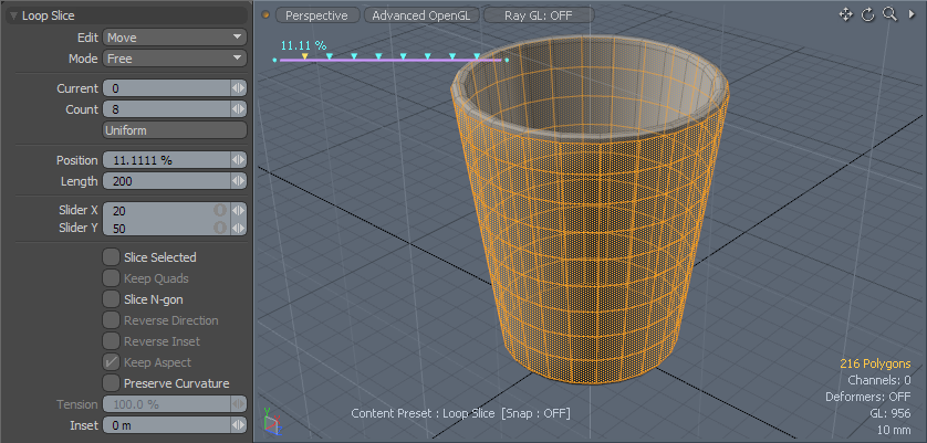
We want our object to be one continuous smooth surface, so in order to add the handle properly, we'll need to add some additional geometric edges to grow the handle from. We could've added subdivisions (additional polygon edges) earlier when we first created the cylinder, but that would've complicated further procedures, so modo allows users to add edges at any time. We'll do this by using the 'Loop Slice' tool. First we'll need to make the selection for our outer surface to apply the slice to, so again select two adjoining polygon faces, this time on the side of the mug and press 'L' to select the loop.
The 'Loop Slice' tool is found under the 'Mesh Edit' sub-tab of the toolbox. Users can also press 'Alt+C' to select the tool. LMB+click in the 3D viewport to activate interactive mode. This will draw a single slice halfway up the side of the mug, we actually want 8 slices, so in the tool properties panel, enter '8' into the 'Count' input field. The model should then look like the following. modo does all the hard math automatically, to make sure all the slices are evenly spaced. Drop the tool again and the selection and press the Spacebar to cycle into 'Edges' mode for the next operation. If any edges are already selected, press 'Esc' to drop them.
In order to give the handle its slightly rounded shape, we'll need to adjust the area where the handle attaches to the body. Select the two edges one span away from both the top and bottom of the mug, illustrated below (making sure they are the edges aligned to the side 'X' axis). Next we'll scale them both lengthwise. I don't want to do it as two separate operations, modo offers special editing modes that allow clusters of selections (or in this case single edges) to have their own independent centers. To activate it, we must modify the 'Action Center' setting. These define where the operation originates from, i.e. where the tool handle is placed, and its axis direction (orientation). To the right of the modes tool bar is the 'Action Center' selector button. LMB+click to open the popup menu and select the 'Local' option. Next, press 'R' to activate the scale tool, and scale only the 'Y' (green) axis to 180% by LMB+clicking over the green handle and dragging the mouse upward. See how both scale from their own center in only one application, that's pretty cool.
The handle isn't quite as thick as these two shapes suggest, so let's bevel them inward somewhat to make a more reasonable sized handle shape. Toggle into 'Polygons' mode, and select the polygons flanking the edges you just scaled (using the methods you learned above). Activate the polygon Bevel tool; 'Shift-B', LMB+click in the 3D viewport (don't be alarmed if the tool handles doesn't appear in the correct location, it will still work correctly). Adjust the 'Inset' (red) handle to 3mm, like before, press 'Shift' and LMB+click somewhere in the 3D viewport to reset the bevel tool, then bevel outward 5mm and drop the tool.
The height of each shape is a little tall, so lets scale it down some. I want to add to the selection here, and modo offers some shortcuts for doing just that. With the 4 polygons still selected, press the 'Shift+Up Arrow' key on the keyboard. (The arrow keys are usually in a cluster for all four directions, or located in numeric keypad working via a toggle key). This will grow the selection one step by selecting all adjoining polygons. Neat. Now, press 'R' to activate the 'Scale' tool and scale just the height of the handle buds to 75% on the 'Y' (green) axis ('Local' Action Center is still active from the earlier procedure, so you should be able to scale each one independently with the one action).
The next step is to connect the two buds to each other, modo will do this somewhat automatically, using the Bridge tool, literally growing a bridge of polygons between two selections. But for this to work, the polygon groups need to be facing somewhat toward each other (otherwise modo has no idea how to connect them). This will be the most complex task of modeling the mug, but it shouldn't take more than a few minutes. It's possible to make the selection we want in the 'Perspective' view, but it will be a little bit easier to see the results we want in one of the Orthographic views; this means there will be no perspective, giving us a good look at a single side of the mug.
In the top of the 3D viewport are three capsule shaped buttons (though not like the regular interface buttons for tools and such). LMB+clicking on these buttons open popup menus that provide users a means to customize the viewports display. We just want to adjust the vantage point, so where it says 'Perspective', LMB+click on the button and select the 'Front' view. If the rotation of your initial mug matched the one here, you should see the mug with the small handle buds off to the left side. If not, try one of the other views, such as 'Left' or 'Right'.
modo offers another way to select polygons beside the brush selection. It is called a lasso (or marquee) selection, where users draw a shape on the screen and all geometry that is contained entirely within the drawn area will be selected. This is helpful for when a lot of polygons need to be selected, or you don't have a good view of what is to be selected. To make the selection we need, first drop any existing selection first by pressing 'Esc'. Next we'll draw the lasso area. This is done by way of the middle mouse button (MMB). If you're using a mouse that does not have a middle mouse button or equivalent, then you will need to also switch the viewport into 'Wireframe' view. This can be done by selecting the viewport button that says 'Advanced OpenGL' and from the menu, select 'Wireframe'. I'll explain why. modo's behavior (by default) is to only select what users can see in the viewport. It makes sense that you would only want to edit what you see, however, this isn't always the behavior you want because sometimes you do want to edit those unseen or rear facing polygons, so there are two distinct methods for lasso selection geometry, the rights mouse button (RMB) lasso selects only what is seen, and the middle mouse button (MMB) selects through the model. When switching to wireframe mode, the rear facing polygons now become visible so the lasso selection will select through the model, so for that particular mode the behavior is reverse; the MMB will only select the forward facing polygons. Now that you understand the different lasso options, lets make the selection already.
Pressing and holding the MMB, as you drag the mouse you will draw a line on the screen, this is the lasso that selects the polygons. You want to draw the shape just big enough to contain the end of the handle nub. With the two polygons now selected, press 'E' to activate the 'Rotate' tool, and using the round handle for the 'Z' axis (blue circle) rotate the polygons to face upward 20 degrees. Do this same action for the upper nub, but rotate the nub to face downward 20 degrees.
Now to apply the Bridge. Hold down 'Shift' to add to the existing polygon selection, so just the ends of both nubs are now selected. The Bridge tool works by connecting groups of polygons, so the lower group will connect with the upper group. Since they both have identical numbers of outside edges, it will match up very nicely. Activate the Bridge tool on the 'Polygon' subtab of the toolbox.
Polygon Bridge Tool
LMB+click in the 3D viewport to enter interactive mode. A single set of polygons is drawn as a straight line between the groups. That's OK. In the Tool Properties panel, set the 'Segments' value to '10' to add some additional geometry for the bridge to work with, and then adjust the 'Tension' value to '200%' curving the handle further out.
That makes the geometry for the handle. But it doesn't match the shape of the reference image all that closely. modo has some tools specific to deforming a shape so we can twist the geometry that is there into something that more closely resembles the original image (we won't be matching it exactly, this is just a tutorial after all). modo applies a technique called a 'Falloff' to attenuate, or fade the affect any tool has on a selection. Normally when you move geometry, it all moves the same amount, as a single rigid piece, but the falloff lets you move one area more than another, with a soft fade between the two extremes. Users can apply a Falloff manually, but for the sake of simplicity here, we'll be using a tool that employs a falloff natively. First, select the new bridged polygons of the handle using the Lasso selection method. Then, under the 'Deform' subtab of the toolbox select the 'Soft Move' tool.
Soft Move tool
The 'Soft Move' tool requires two actions before it will deform the model properly. The first action will create the 'Falloff' and the second deforms the model. With the tool active RMB+click and drag in the upper left area of the handle itself to define the Falloff radius. Once the radius is created in the view, you can LMB+click and drag any of the handles to make subsequent adjustments (just like with a regular tool). Once you have the Falloff the appropriate shape (it doesn't have to be perfect) LMB+click and drag toward the upper left corner of the 3D viewport to deform the handle selection. One of the great benefits of a Falloff is it is live while the tool is active, so users can LMB+drag on the center handle of the falloff to reposition it and see in realtime the deformation change. You can move the Falloff and adjust the Transform amount till you have a shape you're happy with. Once finished, press 'Q' to drop the tool and keep the deformation.
Now the handle is a continuous extension of the body and almost completely finished. Next, switch from the 'Front' view back to the 'Perspective' view to make the last edit. The bottom of the handle is not as wide as the top, where in the original mug, the handle is an even width along its length. This can be fixed with the scale tool. Before proceeding, select the 'Automatic' Action Center type, disabling the current 'Local' (otherwise the next step won't work as expected). This centers the action origin at the tool handles location and keeps the axis alignment upright. We'll also use another modo selection shortcut to make quick work of this edit. modo has the ability to figure out what you want to select next based on the last couple selections. Its called selecting the next plausible element. If you paint select just the first two polygons at the base of the handle and then press the 'Up Arrow' key, modo will continue selecting the next logical polygon in the loop. Each time the button is pressed it will add another element to the selection. Select the entire side of the handle this way and then activate the 'Scale' tool (R key). Scale the selection to 0% on just the 'Z' axis. This can be done easily using the interactive handle when the 'Negative Scale' option is disabled in the tools properties panel. Apply this operation to both sides of the handle. This will equalize and straighten them finishing off the mug.
The last operation is to apply Subdivision Surfaces smoothing to the model by pressing the 'Tab' key. This adds additional polygons to the model that are like virtual geometry controlled by the base low-resolution mesh. The new smooth surface looks much more like the original model reference, so all that is left is to apply a material tag for surfacing the mug in the next section. Press the 'M' key opening the 'Set Material' dialog. Assign a name to the mug, adjust the color to taste and press 'OK'. Ensure no polygons were selected or else the tag will only apply to the polygons that were, which is another good point to bring up. In modo there are implied selection, they are all covered in the modeling section of this documentation, but the most important one is that when no polygons (or any geometry components for that matter) are selected, then they are all considered selected, so any operation applied, applies to everything, hence why having no polygons selected when assigning the material applies to all the geometry. Once done, save your model.
In this second section, you learned about slicing geometry, adding edges to use for additional modeling tasks, using some more advanced tools, like 'Bridge' and had some basic experience with using a falloff to deform the handle, also some additional shortcuts to use when selecting geometry and what an implied selection is. In the next section, we'll set up a simple scene and render out our mug into a finished image.

