
The 3D viewports give users a means to visually manipulate items and their geometric components. Great for laying out models and scenes, but not so useful for setting up relationships between Items and Channels for animation, the domain of rigging. Rigging is the process, or rather the art of making simple controls for complex actions. These controls are built by the linking of channels, modifiers, constraints and any of the other various Items that users have at their disposal. The building of these controllers is done in the Schematic viewport, where elements are visually linked, providing a more intuitive and powerful way to build and rig animated scenes. Uses for these types of links could be as simple as making a wheel spin as a car body moves, or having a muscle shape morph increase as a joint is bent, to something far more complex where all the gears of a clock would spin appropriately, relative to a single second hand rotating. The Schematic viewport is used mainly in conjunction with the Channels viewport, and works by linking channels together via a drag and drop process.
Navigating within the Viewport
The default Schematic view's use is similar to that of the UV view, where users are viewing and working with flat 2D representations of the information. Users can navigate the view of complex node graphs by way of the navigation widgets in the upper right corner of the viewport. LMB+click and drag on the arrow widget to pan the view, clicking the magnifying glass widget zooms the view. Users can also use the familiar keyboard shortcuts to navigate, Alt+LMB click and drag to pan, and Ctrl+Alt+LMB click and drag to zoom. Alternately, users can MMB drag to pan and roll the mouse wheel to zoom.

TIP: Keep in mind that the Schematic view is just another viewport, and therefore can be split to show multiple views or even cloned to show a Workspace in one, and the contents of an Assembly in another, for simultaneous editing.
Adding and Arranging Nodes
When first opening the Schematic view, found in the 'Setup' interface layout, users are presented with an empty workspace, modo needs users to first tell it what elements they wish to work with. To add the necessary elements users can use drag and drop functionality, dragging any item from the 3D viewport, Items list or Channels list and dropping it directly into the Schematic view window. Multiple items can be added by holding down the 'Shift' key, and selecting multiple elements prior to dragging and dropping them. Users can also press the 'Add Selected' button found toward the top of the Schematic window.
Additional components, such as modifiers or constraints, can be added with the 'Add...' button found toward the upper right side of the viewport. LMB+clicking on it will open the menu with a listing of all the different available item types. LMB+clicking on a menu item will select the desired element, adding it to the current Schematic workspace (as well as the the Items list). When adding Channels, they can be dropped anywhere in the viewport, and will automatically add themselves to their respective items (adding the associated Item node as well, if it wasn't already there).
Once added, elements are represented by a gray rectangular box, referred to as a 'node'. In its most basic form the node is a bar with an icon and title, (with the same name as in the Items list). As related channels are added, the box will expand to encompass all associated Channels. User will find it easier to work with the nodes by organizing them and arranging them in the view. This can be accomplished by LMB+clicking on the node header and dragging it to a new position, then releasing the mouse button to place the element. modo will try to snap positions to surrounding nodes to make it easier to place and align nodes for an orderly schematic.
To remove a node, use the context menu, by RMB+clicking on the node header and choosing the 'Remove Node' option or by selecting the node and pressing the 'Backspace' key. Ctrl+Backspace will remove all related nodes (when the 'Separate Channels' options has been applied). Shift+Backspace will remove all nodes in the current workspace.
TIP: When adding items to the schematic view, if Channel Links or (custom) User Channels are already present, the related Channels will be automatically added to the node.
Defining and Editing Node Links
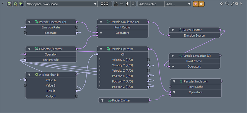
Links are created between node connectors with a line representing their association (once connected, node layouts are referred to as a node graph). There are two types of connectors that can be linked in the Schematic view between nodes, Channel links, represented by circles, and Relationship links, represented by diamonds. Channel links can be thought of like pipes, with data flowing from the output connector of a node (the right hand side connections) to the input connector of the target (the left hand side connections). Relationship connection are a little different in that they simply represent a link between the two nodes. Keep in mind that 'channels' can only be connected to 'channels' and 'relationships' can only be connected to 'relationships'. Beyond that, the connections must be compatible as well, as it wouldn't be possible to connect a boolean channel with a matrix channel. Luckily, modo will only allow correct connections, reducing errors.
To create a link between connectors, simply LMB+click and drag on any connector and drag the resulting line to its intended target connector. If the link is legal the line will turn green when hovering over the target. Illegal connection (ones modo won't allow) will change the line to red. For all legal connections, releasing the mouse button will create the link between connectors. When the line turns yellow while hovering over an existing connection, it means it will replace the connection. Multiple node links can be created simultaneously by holding shift to multi-select channels and then holding shift again while LMB+clicking and dragging one of the selected channels toward its target and releasing the mouse.
Existing node links can be moved by LMB+clicking on either end of a link and dragging the line to a new target and releasing the mouse. Selecting any link prior to creating a new item will automatically link the element inline to the selected link. Removing links is done by selecting the line itself, by LMB+clicking over it changing it to an orange color, and then pressing the delete key or by pressing 'Ctrl' and LMB+clicking the link directly, removing it.
Often times modo will have generated a link automatically, such as when creating simple Particle Simulations. When adding any pre-linked elements to the Schematic viewport, connectors with linked elements not present in the view will be highlighted with a yellow outline signifying the (invisible) connection. The connected element can be made visible by LMB+double clicking the highlighted connector.
When working with existing links, users can hover the mouse pointer over channel row to show original and current (driven) values for a connector. This allows the user to see the current value for the channel itself and see the computed value produced by linked elements. Hovering over an existing link's line will highlight it and display it in the foreground, with the tool tip also showing the connected node's icons on channel row for the channel's type (scalar, vector, matrix, string). Users can also in-line edit node names and channel values by simply LMB+clicking on the name/value and entering a new value to the resulting field.
Workspace and Assembly Navigation
There are two main view types in the Schematic viewport, 'Workspaces' and 'Assemblies'. A 'Workspace' is the main area where users will create and work on node graph setups. This is also the area where users can experiment and examine existing scene setups. Only a single node graph can be visible at any one time in a single Schematic viewport, and visibility is defined by the view navigation buttons in the upper area of the viewport. Users can create and view as many separate Workspaces as desired, compartmentalizing them in hierarchies as necessary for organizing scenes. Any node graph, or portion of a node graph created within a Workspace can be extracted into an individual 'Assembly'. Assemblies can be viewed and navigated in the same way as Workspaces.
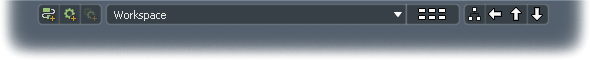
The selector menu (the wide button) can be LMB+clicked to open a popup menu, allowing users to select from the currently available Workspaces/Assemblies. When the menu is opened, it shows all the root level Workspaces and Assemblies defined in the scene, i.e. those that have no parent Assemblies (children will only be visible within their own hierarchies). Selecting the desired menu option will make the chosen graph visible in the viewport (active). The buttons surrounding the selector menu allow users to create new Workspaces/Assemblies, and navigate and define hierarchies for multi Workspace/Assembly setups.
LMB+clicking on the button with the array of six stacked tiny white boxes will enter 'Overview' mode, a broad view of all the Workspaces and Assemblies in the current scene. Here users can define hierarchies by LMB+click and dragging any Workspace or Assembly onto that of another, making it a child of the item it is dropped onto. Assemblies/Workspaces that have a hierarchy beneath them have a small ' hierarchy badge' icon drawn in the lower right corner of their Overview node graphic denoting the fact that it contain child Workspaces or Assemblies. Users can also navigate to any existing Workspace/Assembly from this view by LMB+double clicking on a Workspace or Assembly node directly, making it the active Workspace.
Users can navigate hierarchies of Workspaces/Assemblies directly with the arrow buttons on the right side of the selector menu. The first button will display a hierarchy layout of the current active Workspace or Assembly. Within this view, users can see how Workspaces/Assemblies are related, and can LMB+double click to make any node active in the viewport. The left pointing arrow will navigate back to the last view (like the 'back' button on a web browser), the up arrow travels to the parent item and the down arrow travels to the child item (keyboard shortcut 'Alt+Up/Down Arrow' keys, Alt+Left/Right Arrow' keys will navigate between sibling nodes in a hierarchy).
Assemblies are a way of packaging up parts of a graph into a single node, simplifying a node layout graph or a way to create re-usable assets withing a scene (or a Preset that can be easily placed in other scenes). The contents of any 'Assembly', or 'Sub-Assembly' can be viewed by LMB+double clicking on them within the Workspace or the Overview. This shows the contents of the Assembly, identified by the darker background and the input/output channels. The input/output channels are located on either side of the graph and are color coded, green for input and purple for output. Clicking on the '+' (plus) icon button in these areas will create a new user channel on the Assembly which can be used as additional inputs or outputs to the Assemblies contents.
Instancing and Mirroring Assemblies
Instancing Assemblies provides a means of creating multiple copies of a setup (or rig) without the need to duplicate the entire contents of the Assembly or having to manually update all the copies if the original Assembly is changed. The user identifies which items are inputs and which are outputs in the original Assembly. For example, a suspension rig might have the root item that's parented to the chassis as an input and the hub or wheel as an output. When the Assembly is instanced only the items marked as inputs or outputs are instanced (replicas for certain Items will be an option). An option on the Assembly instance allows it to be mirrored; in the above example this enables the suspension setup to be created for the other side of the car automatically and any changes to the original setup will be propagated to the mirrored instance.
To instance an Assembly, either RMB+click on the Assembly node within a Workspace, or within the Overview and from the contextual menu, select the 'Instance' command. This will create an instanced copy of the items in the Items list, but the node itself will have a bracketed number reflecting the number of Instances, such as "MyAssembly [+3]" for three Instances. LMB+double click on the Assembly opens it, where along the bottom of the viewport, the Instances will show as numbered Assembly nodes. RMB+clicking on a particular Instance will open the contextual menu and users can select the 'Mirror' command and then choose how the Assembly will be mirrored, such as the axis and whether to mirror over the Local (center position) axis or the World position (origin) axis.
Assembly Inputs & Outputs
Inputs are the Items or Channels that drive the inner workings of the Assembly, most often these are the items that the user manipulates to control the rig and the items used to position and orient the rig within the scene (such as an Assembly Root Item). An instanced Assembly that has no inputs defined will be a direct copy of the source Assembly, and it will sit directly on top of its source in the 3D views, where any motion on the source Assembly will be mimicked in its instances. Inputs then are the means by which independent behavior can be brought to the instanced Assemblies. Assigning the Root Item of an Assembly as an 'Input' will allow all the Assemblies instances to be positioned independently in the scene for example.
Another example would be assigning the IK goal of an IK chain as an input, hence allowing all the instances to be controlled independently. Items can be assigned as an input by RMB+clicking on the item node header and choosing 'Assign Item as Input' from the contextual menu. Individual channels can also be assigned as inputs for an Assembly. RMB+clicking on the Channel and selecting 'Expose Channel' from the context menu. This creates a new 'User Channel' of the same type and adds it to the Assembly Group item and assigns a Channel Link made to the selected channel. This also allows Assembly groups to be used as 'sub-assemblies' or black boxes, where their internals are controlled by a few input/output channels.
'Outputs' in an Assembly are Items that are driven, either directly or indirectly by the Assembly, and these items will themselves be instanced and visible in the 3D views. Mesh items default as Outputs in an Assembly, other Items can be assigned as an 'Output' by RMB+clicking on the item node header and choosing 'Assign Item as Output' from the contextual menu This will add an instance of that item to each of the Assembly instances in the scene. Output items in the instanced Assemblies cannot be manipulated directly, e.g. by using the transform tool, however they will inherit animation from their source items. An item may not be both an input and output for an assembly. As mentioned above this means that items assigned as outputs cannot be manipulated in any instances of the Assembly. However, if one or more of the transform items for the output are added as inputs to the assembly then FK manipulation, channel linking etc will work.
TIP: Assembly Root Items are special Locators that can help keep the Items in an Assembly organized and makes the Assembly easier to manipulate in the Scene (especially when working with Instanced and Mirrored Assemblies). Any Items within the Assembly should be Parented to this Root element. Users can create an Assembly Root Item within a Workspace or Assembly by RMB+clicking and selecting the "Create Assembly Root Item" option, or by RMB+clicking on the Node header for an existing Locator and selecting the "Assign as Assembly Root Item" command. Assembly Root Items are highlighted in color so they are easy to identify within the Schematic view.
Viewport Options
The options that control the display of elements within the viewport found under the Options icon. LMB+click the gear icon in the upper right corner of the viewport to open the Options panel. All options are toggles, where a check mark enables the function and no check mark disables the function.
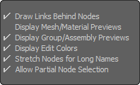 Draw Links Behind Nodes: When this option is enabled, the resulting link lines will be drawn behind the node panels, hover the mouse pointer directly over the connection line to temporarily make it visible in front of the node individually. When disabled the lines will always draw in front of the nodes.
Display Mesh/Material Preview: When this option is enabled a quick preview icon will be generated and displayed in the header of the node panel for Meshes and Materials. When disabled the icon will not be generated or displayed.
Display Group Assembly Preview: When this option is enabled a quick preview icon will be generated and displayed in the header of the node panel for Groups and Assemblies. When disabled the icon will not be generated or displayed.
Display Edit Colors: When this option is enabled, item 'Editor Colors' will be displayed as node panel outlines, when disabled the outline colors will not be displayed (but items layers will still be colored in the Items List).
Stretch Nodes for Long Names: When this option is enabled the width of the node panels will widen to accommodate long names. When disabled, node names will be truncated to fit the standard node width, hovering the mouse pointer directly over then name will always open a tool-tip popup with the long name visible.
Allow Partial Node Selection: When this option is enabled, marquee selections in the Workspace will select any node that the marquee box touches, when disabled only nodes that are fully enclosed in the marquee box are selected.
Contextual Menus
The Schematic viewport has a wide variety of contextual menu that open under a RMB+click over a specific element.
Depending on what element you click over, you'll get a different menu with options specific to that task. The Following section details all the commands found within these menus.
RMB+clicking an empty area of the Workspace/Assembly background opens a Workspace contextual menu-
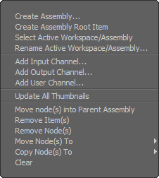 Create Assembly: When one or more nodes are selected, the Create Assembly option opens the 'Schematic Create Assembly' dialog that allows users to package the nodes into a single Assembly node that simplifies the graph and makes the setting more easily portable for reuse elsewhere. Users can LMB+double click the resulting Assembly to view and edit its contents.
Create Assembly Root Item: This command creates a special Locator item that can be assigned as the parent in a hierarchy to the items in an Assembly (therefore becoming the root of all the elements within). This makes the elements easier to manipulate together in the 3D viewport, especially when working with instanced and mirrored Assemblies (must be assigned as an Input Item). The Assembly Root Item draws in the schematic viewport with a green highlight, and in the 3D viewports as a green box for easy identification.
Select Active Workspace/Assembly: This command will select the active Workspace/Assembly in the 'Groups' palette; all related elements will be highlighted denoting its selected state.
Rename Active Workspace/Assembly: This command opens a dialog box allowing users to rename the current active Workspace or Assembly. Once changed, the name will be visible in the various menus and in the Overview view.
Add Input/Output Channel: This command opens the 'Add User Channel' dialog and connects the resulting channel as an exposed Input or Output to the Assembly.
Add User Channel: This command opens the 'Add User Channel' dialog box, allowing users to create custom channel types that can be connected for various rigging purposes. The 'Add User Channel' feature is covered further in the 'Add User Channel' page of the documentation.
Update All Thumbnails: This command forces a refresh of all node icons, updating them to their current states, if they have changed. The viewport option 'Display Mesh/Material Preview' must be enabled in order to see icons on nodes.
Move Node(s) into Parent Assembly: A shortcut command that is used to move one or more nodes from the current Assembly to its Parent.
Remove Item(s): This command removes the selected Item(s) from the Scene.
Remove Node(s): This command removes the selected nodes(s) from the Schematic viewport.
Move Node(s) To: This command opens a fly-out menu that lists all the current Workspaces/Assemblies, allowing users to move all selected elements to the selected location.
Copy Node(s) To: This command opens a fly-out menu that lists all the current Workspaces/Assemblies, allowing users to copy all selected elements to the selected location.
Clear: This command removes all nodes from the Workspace/Assembly, essentially resetting the viewport to its initial empty state.
RMB+clicking while hovering the mouse pointer directly over a link connection line opens this contextual menu-
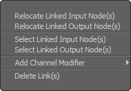 Relocate Linked Input/Output Nodes(s): This command will auto position the node, within the viewport of Schematic view, for the incoming or outgoing link(s).
Select Linked Input/Output Node(s): These commands can be used to automatically select the nodes of the incoming or outgoing links.
Add Channel Modifier: This option opens a fly-out menu of all the various channel modifiers that can be added to a schematic graph.
Delete Link(s): This command removes the connector line between nodes, eliminating the link.
RMB+clicking directly over a node header (title) opens this contextual menu-
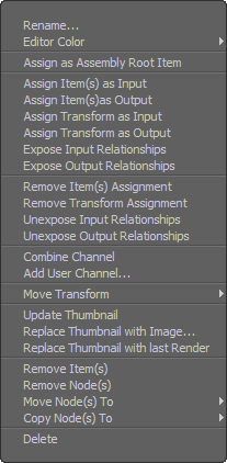 Rename: This command allows users to inline edit the name of the target Assembly.
Editor Color: This option defines a layer color for identifying and organizing items, that displays in the Schematic viewport as a colored outline around the node panel.
Assign as Assembly Root Item: This command converts an existing Locator item to an Assembly Root Item Locator. These are a special kind of Locator that can be assigned as the parent in a hierarchy to the items in an Assembly (therefore becoming the root of all the elements within). This makes the elements easier to manipulate together in the 3D viewport, especially when working with instanced and mirrored Assemblies (must be assigned as an Input Item). The Assembly Root Item draws in the schematic viewport with a green highlight, and in the 3D viewports as a green box for easy identification.
Assign Item(s) as Input: This command allows users to assign one or more of the Items within an Assembly as an Input which allows users to control which of the items within the Assembly will be instanced with the Assembly (appearing in the Items List as Instances). Items designated as Inputs can also be independently transformed as instances (relative to their root).
If the Assembly Root Item is defined as the Input, it will allow the instanced Assembly to be positioned independently of its source. If additional items are defined as Inputs they will appear in the Items List and users can select them and transform them independently as well (relative to their root).
Assign Item(s) as Output: This command allows users to assign one or more of the Items in an Assembly as an Output, which allows users to control which Items within the Assembly are instanced with the Assembly (appearing in the Items list as Instances); Mesh Items default to being outputs. Items designated as Outputs cannot be independently transformed in the resulting Instances, but are driven by the source Item, duplicating its transforms. If parented to a hierarchy under an Assembly Root Item, the Instanced Item will transform relative to the roots position (where the Root is defined as an Input).
Assign Transform as Input/Output: Allows Selected Transform Channels, such as Position, Rotate ans Scale to be designated as 'Inputs' or 'Outputs', independent of the Items designation.
Expose Input/Output Relationship: This command exposes a relationship connector on a node within the Assembly so it can drive or be driven from outside the Assembly.
Remove Item Assignments: Removes any 'Input' or 'Output' assignment applied to an Item.
Remove Transform Assignments: Removes any transform 'Input' or 'Output' assignment applied to an Items transform channels.
Unexpose Input/Output Relationships: This command removes an exposed relationship, preventing the channel from driving or being driven from outside the Assembly.
Combine Channel: This command moves all selected Channels for the selected item from their original nodes into the recently selected node.
Add User Channel: This command opens the 'Add User Channel' dialog box, allowing users to create custom channel types that can be connected for various purposes. The 'Add User Channel' feature is covered further in the 'Add User Channel' page of the documentation.
Move Transform: For Items that have related Transforms, this command allows users to change the order by first selecting the target transform channel and then RMB+clicking to open the contextual menu and selecting the appropriate command under 'Move Transform'.
Update Thumbnail: This command forces a refresh on the thumbnail image. The viewport option 'Display Mesh/Material Preview' must be enabled in order to see icons on nodes.
Replace Thumbnail with Image: This command Opens an OS dialog allowing users to select a saved image that will replace the current icon representing the node. If the selected image is larger than 128x128 in resolution, it will be re-sampled to that size.
Replace Thumbnail with last Render: This command will replace the current icon image with the last render in the render list of the Render Display viewport. Render will need to have been created during the current modo session. If the rendered image is larger than 128x128 in resolution, it will be re-sampled to that size.
Remove Node(s): This command removes the selected nodes(s) from the Schematic viewport.
Move Node(s) To: This command opens a fly-out menu that lists all the current Workspaces/Assemblies, allowing users to move all selected elements to the selected location.
Copy Node(s) To: This command opens a fly-out menu that lists all the current Workspaces/Assemblies, allowing users to copy all selected elements to the selected location.
Delete: This command removes the node and its associated item from the scene.
RMB+clicking directly over a node header (title) for an Assembly opens this contextual menu-
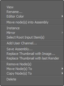 View: This command switches to view any selected Assembly.
Rename: This command allows users to inline edit the name of the target Assembly.
Editor Color: This option defines a layer color for identifying and organizing items, that displays in the Schematic viewport as a colored outline around the node panel.
Move node(s) into Assembly: This command will move the selected node(s) into the Selected Assembly.
Instance: This option allows users to create a virtual copy of an Assembly (that references its master Assembly) that can be used elsewhere in a schematic graph, Workspace or Assembly. This option can only be applied to an Assembly node, from the Workspace or in the Overview.
Mirror: The 'Mirror' option allows users to invert an Instanced Assembly across the user defined axis, useful for making multiple identical Items that mirror, like the wheels of a car, or the IK leg setup of a spider. Selecting the 'Mirror' option will open a flyout menu for defining between the Local axis (the root items center point) or the World axis (world origin). If there is an Assembly Root item in the Assembly then it's location and orientation are used as the mirror axis.
To Mirror an Assembly it must first be instanced. Then by opening the root Assembly (LMB+double click in the Assembly in the Overview), the individual Instances will appear in a new section toward the bottom of the viewport. Then RMB+clicking on the target instance, users can then select the 'Mirror' option from the contextual menu. Once mirroring is assigned, users can position the resulting mirrored assembly using the exposed channels or by positioning the root Locator.
Select Root Input Item(s): Selects all Locator items in the Assembly that are assigned as inputs and which have no parent present in the Assembly.
Add User Channel: This command opens the 'Add User Channel' dialog box, allowing users to create custom channel types that can be connected for various purposes. The 'Add User Channel' feature is covered further in the 'Add User Channel' page of the documentation.
Save Assembly: This command opens an OS dialog panel allowing users to save the Assembly as a preset. If saved to the Presets directly, users can then later drag-and-drop the resulting Assembly Preset from the 'Preset Browser' directly into a new scene.
Replace Thumbnail with Image: This command Opens an OS dialog allowing users to select a saved image that will replace the current icon representing the node. If the selected image is larger than 128x128 in resolution, it will be re-sampled to that size.
Replace Thumbnail with last Render: This command will replace the current icon image with the last render in the render list of the Render Display viewport. Render will need to have been created during the current modo session. If the rendered image is larger than 128x128 in resolution, it will be re-sampled to that size.
Remove Node(s): This command removes the selected nodes(s) from the Schematic viewport.
Move Node(s) To: This command opens a fly-out menu that lists all the current Workspaces/Assemblies, allowing users to move all selected elements to the selected location.
Copy Node(s) To: This command opens a fly-out menu that lists all the current Workspaces/Assemblies, allowing users to copy all selected elements to the selected location.
Delete: This command removes the 'Assembly' from the scene and all items contained within.
RMB+clicking directly over a node connector dot opens this contextual menu (for both input/outputs)-
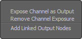 Expose Channel as Input/Output: This command makes the selected Channel visible on the Assembly node so it can be linked to by other external nodes.
Remove Channel Exposure: This command hides exposed Channels so they are no longer visible on the Assembly node.
Add Linked Output Nodes: This command finds any nodes that are linked to the selected Channels / Relationships and brings them into the current Workspace / Assembly.
RMB+clicking directly over any Channel inside a node panel opens this contextual menu-
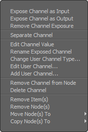 Expose Channel as Input/Output: This command makes the selected Channel visible on the Assembly node so it can be liked to by other external nodes.
Remove Channel Exposure: This command hides exposed Channels so they are no longer visible on the Assembly node.
Separate Channel: This command will separate the channels out from a node to their own node panel, that can be positioned independently for easier graph construction. Three small dots will draw under both node panels indicating the separated state.
Edit Channel Value: This option allows the user to inline edit the Channel value that is RMB+clicked to open the contextual menu.
Rename Exposed Channel: This option allows the user to inline edit any User Channel name that is RMB+clicked to open the contextual menu.
Change User Channel Types: This option opens the 'Change Channel Type' dialog allowing users to change the type of a User Channel, such as a 'Scalar' to a 'Boolean'.
Edit User Channel: This option opens a popover form allowing users to edit the properties of a User Channel definition.
Add User Channel:This command opens the 'Add User Channel' dialog box, allowing users to create custom channel types that can be connected for various purposes. The 'Add User Channel' feature is covered further in the 'Add User Channel' page of the documentation.
Remove Channels from Node: This command will remove the channels from the channel row of the node panel, but the channels will still be active within the Channels viewport of the related Item.
Delete Channel: This command is used to remove User Channels that have been created for the selected item.
Remove Item(s): This command removes the selected Item(s) from the Scene.
Remove Node(s): This command removes the selected nodes(s) from the Schematic viewport.
Move Node(s) To: This command opens a fly-out menu that lists all the current Workspaces/Assemblies, allowing users to move all selected elements to the selected location.
Copy Node(s) To: This command opens a fly-out menu that lists all the current Workspaces/Assemblies, allowing users to copy all selected elements to the selected location.
![]() Create New Workspace
Create New Workspace
Pressing the 'Create New Workspace' button opens the 'New Schematic Workspace' dialog box where users can create and name the new empty Workspace and define if they want it to become the currently active Workspace. In a new scene, if there is nothing in the active Workspace when a new Workspace is created (i.e. it is empty), the newly created Workspace will become the initial workspace, all other new ones thereafter will be in addition to the initial Workspace.

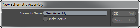
![]() Create New Assembly
Create New Assembly
Pressing the 'Create New Assembly' button opens the 'New Schematic Assembly' dialog box where users can create and name a new empty Assembly and define if they want it to become the currently active Assembly for editing.
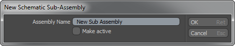
![]() Create New Sub-Assembly
Create New Sub-Assembly
Pressing this button opens the 'New Schematic Sub-Assembly' dialog box where users can create and name a new empty Sub-Assembly (Child in the hierarchy of the currently active Assembly) and define if they want it to become the currently active Assembly for editing.
Creating Assemblies from a Graph
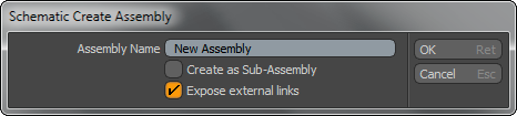
Once the user has a working graph or even a portion of a graph setup, an Assembly can be created from it. Assemblies are useful to simplify very complex graph layouts, by compartmentalizing multiple nodes into a single node. It is also a good way of separating out parts of a graph for organization, allowing users the ability to work on each area independently. Assemblies can also be a useful asset that can be saved out and re-used later. To create an Assembly select each of the nodes in the graph that you want to include and then right click on a blank area of the background and choose "Create Assembly…" from the contextual menu. Provide a name in the dialog that's displayed. The new Assembly can be created in two ways, as a normal 'Assembly' or as a 'Sub-Assembly', determined by the "Create as Sub-Assembly" option. When enabled this option will create an Assembly that becomes part of the current graph, otherwise a standalone root level Assembly will be created. In both cases the selected nodes are removed from the graph and added to the new Assembly. The last option, "Expose External Channels" is only applicable to sub-groups, this will create channels on the new group for each channel link to or from a channel within the group. This is very useful for creating Assemblies that can be re-used elsewhere, a kind of black box that can be connected up without knowing about the internals. Click 'OK' to create the new Assembly, if it was a standalone Assembly the view will change into the 'Assembly' view to show it's contents.
Creating Sub-Assembly Walk-through
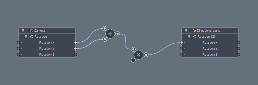
Select the elements that make up the sub assembly, here it is the 'add' and 'multiply' nodes.
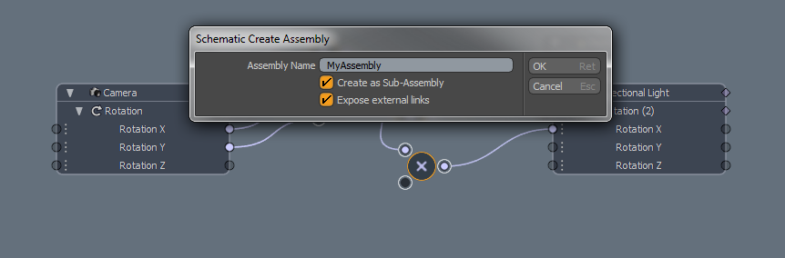
RMB+click on an open area of the workspace and choose 'Create Assembly' from the context menu.
Clicking 'OK' changes the selected elements into the Sub-Assembly.
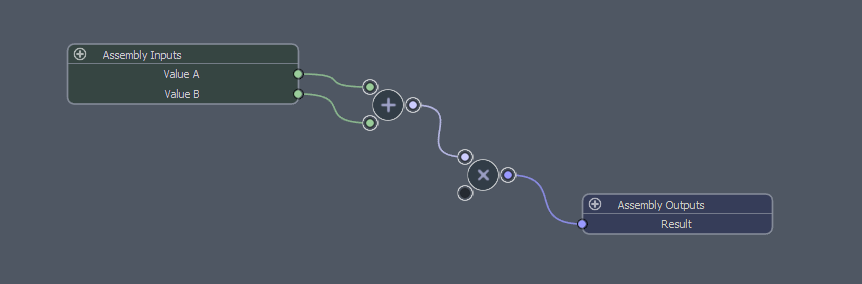
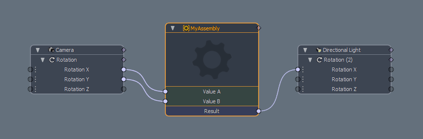
The contents of any Sub-Assembly can be viewed by LMB+double clicking on the names Assembly node.
Note that within the scene file structure, the actual data for schematic graphs is stored in a special Group type, in the Groups viewport. Within that viewport users can see the options for 'Assemblies', these are the same groups that are displayed in the Assembly mode of the schematic view, new assemblies can be created via the 'New Group' button. This will create a new blank display in the schematic. The schematic always shows the most recently selected 'Assembly' ('Workspaces', while viewable, cannot be created within the Groups viewport).

INFO: The concept of the Schematic viewport is easy enough to understand, creating links from one node to another, but the concept of rigging and animation control building overall is very complex and unfortunately well beyond the scope of this documentation.

