
Mesh Items can also be considered geometry layers as this is how they appear in the Item List. Mesh Items contain vertices, edges and polygons and are usually the hero of your project. These are your models. As with any Item, Meshes have Item level transforms for Position, Rotation and Scale. Unlike any other Item, the Mesh item also has transforms at the component level which is how you typically do modeling operations. The difference between component edits and Item level edits is very important.
Component transforms are simply editing vertices, edges and polygon information on the mesh. If nothing is selected, modo considers everything to be selected so that you can easily activate a tool such as Move and drag around an entire mesh without selecting all the polygons or vertices first. When you edit the mesh this way you are adding vertex map data to every vertex in the mesh. Think of Item based transforms as editing the layer that contains the mesh data itself rather than the geometry within the layer. This is why Item transforms are limited to rigid moves, rotates and scales and do not allow any of the deformation available at the component level. Item level transforms are also wicked fast as the edit is handled at a higher level. One easy way to know if you are performing an Item or component level edit is to check your selection mode. If you are in Vertex, Edge or Polygon mode you are performing component edits. Only when you are in Item mode can you perform an Item level transform.
If you find that you have performed Item level transforms when you intended to do component transforms, you can use the Freeze transform option found on the Items Property form. This handy command makes it useful to perform Item level transforms for performance on heavy meshes and then simply push the transform information into the vertices by Freezing after the edit.
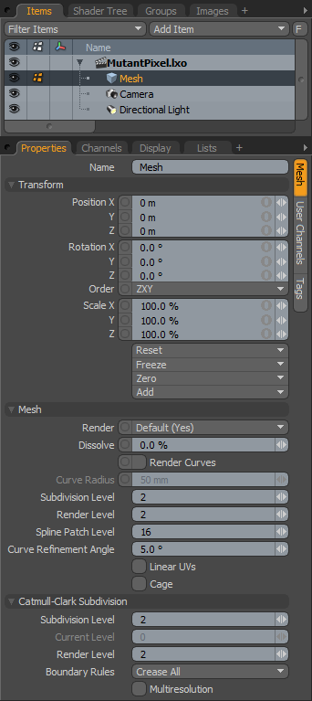
Each Mesh item layer can be considered its own object within a scene, with its own transforms, subdivision settings and its own UV Maps. Users can add additional Mesh items to a scene by pressing the 'Add Item' button in the upper right corner of the Items list and select the 'Mesh' option, additionally users can use the menu bar command "Geometry > New Mesh Item". Finally, users can also easily create an empty mesh layer by simply pressing the 'n' keyboard shortcut while in the modeling interface tabs. Once selected a number of attributes become available for editing within the Properties viewport-
 Name: This data field displays the current item name. Users may easily change it by LMB-clicking within the field and typing the new name.
Transform--
Position: An Item transform that allows the user to numerically position the item in XYZ space. By default, Position transforms originates from the Center position.
Rotation: An Item transform that allows the user to numerically set the rotation of the item. By default, Rotation transforms originate from the Center position.
Order: Allows the user to set the order that rotations are applied to the camera item. Changing the order that rotations are applied can sometimes help to reduce or eliminate gimbal lock.
Scale: An Item transform that allows the user to numerically set the size of the item. By default, Scale transforms originate from the Center position.
Reset: Resets the selected transform values to (0,0,0) returning the items back to their default state.
Freeze: Returns the items 'Center' position to the world space center (0,0,0) without changing the position of the mesh item itself.
Zero: Resets the chosen transform property values to '0', leaving the 'Center' position and Mesh position intact. This is done by adding a negative transform item to the Mesh items channels.
Add: The 'Add' function will add the selected set of transforms to the channel list. Useful when animating complex motions, providing a layered approach to the transforms.
Mesh--
Render: This drop down menu allows the user to select from 3 choices, when set to 'Default', the user can enable/disable mesh item using the visibility column (eyeball icon) of the item list. When the mesh layer is visible, it contributes to the final rendered scene and when invisible, it will not. On some instances the user may prefer to fix this state, setting the mesh as 'On' (enabled) or 'Off' (disabled) regardless of visibility. Also useful for workflows that auto toggle visibility, saving the user from manually enabling mesh layers for test renders.
Dissolve: The 'Dissolve' function controls the visibility of an item layer, at 0% the item renders normally, utilizing the shader tree settings, values above 0% would fade the visibility of the item layer ramping toward 100% where the item would be completely invisible.
Render Curves: Generally, curves are non-rendering items in a layer meant to facilitate other functions -- hair guides, patching guides, duplication paths and so forth. However, with the 'Curve Radius' set to a value above 0, and the 'Render Curves' function enabled the previously invisible curves renderable. Material tags for surfacing can be applied to curves in the same way they are for regular polygons (by selecting the curve in 'Polygons' mode and assigning a 'Material' tag). Rendered curves essentially become tubes that have several benefits over extruded geometry, they reduce the amount of geometry in the scene since render curves are generated at render time making for a lighter file size and their size is editable and animateable as well. Additionally morph deformations applied to a curve will keep a consistent thickness. Note that because of their procedural nature, they cannot be displaced. Use the 'Curve Extrude' function to make an actual tube when using displacement.
Curve Radius: When 'Render Curves' is enabled, the 'Curve Radius' determines the size of the 'tube' that is generated. The radius is centered around the curve itself, so a setting of 12mm would generate a tube with a 24mm diameter.
Subdivision Level: Any selected geometry within a layer can be converted to a subdivision surface by utilizing the 'Tab' key shortcut. This produces a smoothing effect to the surface, essentially becoming a proxy for the smoothed SDS geometry which cannot be directly edited. The 'Subdivision Level' setting specifies to what degree a SDS model is divided. There are certain functions that override this setting at reder time, such as those for 'Adaptive Subdivision'. Otherwise, when using the Freeze command, the 'Subdivision Level' controls the number of polygons generated as does it control the number of polygons displayed in any 3D viewport. This value can be interactively adjusted with the +/- keys on the number pad when a Mesh item is selected.
Render Level: When 'Adaptive Subdivision' is disabled, users can set a independant 'Render Level' for subdividing their geometry only when any of the 'Render' commands are invoked. This can be helpful in increasing OpenGL viewport performance by setting a low Subdivision Level and a high Render Level, keeping a finely subdivided smooth surface only when the scene is rendered.
Spline Patch Level: Spline patching is a way of parametrically defining a surface with a number of curves. When Patching the curves to define the surface, the 'Spline Patch Level' controls the number of polygons used. These polygons are not directly editable unless one applies the 'Freeze' command found under the menu bar "Geometry > Freeze..."
Curve Refinement Angle: Curve Refinement Angle controls how curves are quantized for display and freezing. This is analogous to the patch resolution for subdivision surfaces.
Linear UVs: modo automatically switches between linear UVs for straight polygonal geometry and smoothed UVs for subdivision surface (SDS) geometry. There may be some instances where an image map created outside of modo utilized linear for an SDS model, in which case enabling 'Linear UVs' will correctly apply the image map to the geometry within modo.
Cage: The 'Cage' option toggles any Subdivision Surface geometry in the current mesh layer. Especially useful in temporarily disabling SDS in complex models without losing the SDS definitions for the geometry.
Subdivision Level: Users may convert any surface into a Catmull-Clark Subdivision Surface by pressing the 'Shift+Tab' key combination. The Catmull-Clark Subdivision Surfaces are superior to regular Subdivision Surface geometry, especially in their handling of edge creasing, however they are more computationally intensive than regular Subdivision Surfaces geometry and require more memory to render. The Subdivision Level controls how finely a surface is subdivided.
Current Level: When the 'Multiresolution' option is enabled, users can use the 'Current Level' option to step up and down through the different levels of subdivisions (up to the maximum level defined by the 'Subdivision Level'). Useful when sculpting providing the ability to add different degrees of detail to a model at different levels.
Render Level: When 'Adaptive Subdivision' is disabled, users can set a independant 'Render Level' for subdividing their geometry only when any of the 'Render' commands are invoked. This can be helpful in increasing OpenGL viewport performance by setting a low Subdivision Level and a high Render Level, keeping a finely subdivided smooth surface only when the scene is rendered.
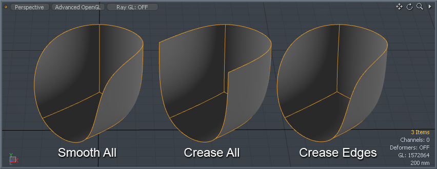
Boundary Rules: The boundary rules determine how to move the points on the boundaries of a Catmull-Clark Subdivison Surface mesh. Creasing will produce a sharper transition between surfaces, smoothing, quite obviously, produces smooth surface transitions. The options are-
Smooth All- All of positions on the boundary are moved by the smooth rule of Pixar Subdivision Surfaces.
Crease All- The points that have two incident edges (valence = 2) are moved by the crease rule, other positions on the boundary are smoothed by two boundary edges.
Crease Edges- The points that have two incident edges (valence = 2) are moved by the smooth rule, other positions on the boundary are smoothed by two boundary edges.
Multiresolution: Only available to a Pixar Subdivision Surfaces model, users can enable this option step up and down through the subdivision levels when sculpting a mesh, allowing users the ability to add varying degrees of detail without obliterating detain present in other levels. Users can adjust the current level using the 'Current Level' option above, or step through the levels using the Multi-res settings in the sculpting toolbox of the 'Paint' interface tab.

