
The Solid Sketch tool provides a quick method for "roughing" out organic shapes. By clicking down nodes Solid Sketch connects the dots with a smooth flowing mesh. Each node can spawn new branches to create complex shapes quickly and easily. For instance, you might create a hand by starting with a single node that branches to five new nodes each having a series of nodes that follow them to create fingers.
When a mesh is created with Solid Sketch, the tool also places two point lines inside the mesh so that when you reactivate the tool it can recover the state of the tool from these two point lines. It should be noted that any additional geometry in the mesh item at that time would be deleted as it clears all polygons prior to activating the tool.
When you click to create a node you can immediately drag to the right and left to scale the node. Once you have released the mouse button you can use the various handles to move, scale, rotate and twist the node. Additionally, holding the Shift key and dragging on the center handle will scale on all three axes.
 Solid Sketch--
Move: Center handle that is always visible even when the node is not selected. This is also the handle you click on to select the node for editing. Clicking and dragging this handle will move the node in the two axes defined by the current workplane. As mentioned earlier, Shift-dragging this handle will change the behavior to scale the node on all three axes uniformly.
Rotate: The rotate handles are the Red, Green and Blue rings around the selected node. These represent rotation around the Z, Y and X axes respectively. To rotate the node simply click and drag on the desired ring handle. The affect of using the rotation handles is to actually move the children nodes of the current node as if the selected node were being reoriented.
Stretch: The red, green and blue squares just outside the rotation rings are used for scaling on the three axes individually. To scale the node on all three axes hold the Shift key while dragging the center most handle.
Twist: The yellow handle allows a simple twisting effect to the node. Twisting the node will not affect the position of the nodes connected to it.
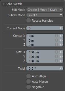
All of these values can be controlled via the tools property form. Further there are additional controls available via the tool properties.
Edit Mode: The default value of "Create|Move|Scale" allows you to create and scale the node on initial click-drag and then use the various handles to control the node further. In this mode you can delete a node by MMB clicking directly on the node. You can also set the Edit Mode to Destroy if you want to quickly click on several nodes to destroy them.
Subdiv Mode: This setting determines how many tessellation levels to apply to the mesh using the SDS algorithm. Setting this value to 0 reveals the polygonal cage. Increasing the value to two will create additional edge loops at each node. This can be particularly useful when creating complex branching from a single node.
Auto Align: With this active each node reorients the geometry it creates to more smoothly blend with the geometry segments around it.
Auto Merge: Since each node typically generates a cube of polygons around it, bunching up nodes close together would cause the mesh to pinch. The Auto Merge setting will reduce a nodes created geometry by merging it into other nodes once they are too close together.
Negative: Off by default, this option causes a node to repel neighboring geometry. This can be useful to create divots in the mesh.

