
Using a two dimensional (flat) screen to create and edit content in 3D space can sometimes feel awkward and unnatural. Software has tried to resolve the disconnect using different solution over the years. The most popular is the four viewport method. Each orthogonal viewport only provides two axes at any given time, eliminating surprises to users as they create and modify geometry in a given scene. Another solution is to require the user to work with tool handles constraining operations performed in a perspective viewport to the same flat 2D axes of the four viewport method. Both of these solutions are reasonable and available in modo. However, modo also employs a third method called the 'Work Plane'.
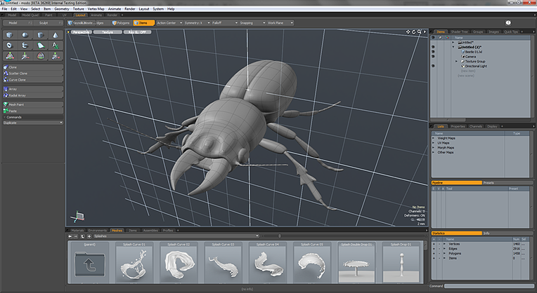
The Work Plane is a white grid that appears in the 3D openGL viewports. In this example above, the Work Plane has been highlighted for emphasis.
The Work Plane is an adaptive modeling aid that automatically adjusts itself to match the two major axes most closely aligned to the users screen axis, represented by a white grid within any of the openGL viewports. When you rotate the Perspective viewport the Work Plane will snap to one the dominant planes, XY, XZ or XY. Action Centers often use the Work Plane position to determine the center and axis of tools. When hauling, many tools also use the work plane to determine the axes of operation as well when this information cannot be derived from a specific tool handle.
While the default mode for the work plane is to automatically adjust to the screen rotation, the work plane can also be locked and used as a construction plane, when applied as such, the Work Plane effectively positions the entire modo universe to that fixed angle and position. There are a number of methods for manually setting the Work Plane to a specific center and axis. The work plane can be easily locked to a specific major axis and position, or you can snap the Work Plane to selected geometry or even just to the polygons directly under the mouse. This level of flexibility and control provides users with an incredibly fluid and rich set of options for editing their workspace.
Mastering the Work Plane will allow users the freedom to do most, if not all, of their modeling in a single perspective viewport. That means more screen real estate for viewing the geometry and performing the various modeling tasks allowing users to work more fluidly and accurately. Users are encouraged to experiment with the Work Planes when using tools and hauling, so they can get a better grasp of its behaviors and use them to their advantage.
Work Plane Controls
The Work Plane is a persistent function of the 3D viewports, and is visible by default, users can toggle its display under the visibility controls of the viewport options panel that pops up when hovering the mouse pointer over a viewport and pressing the 'o' key. The controls for the Work Plane are conveniently located in the interface under the Work Plane menu button, or within the menu bar under the "Edit > Work Plane" menu. Users can also use the 'Home" key to dynamically position the Work Plane to any geometry directly under the mouse pointer, centering under where the pointer tip intersects the polygons surface and aligning it to the polygons normal direction.
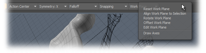
Invoking this command returns the Work Plane to it's default behavior. Only applies if the Work Plane has been aligned as a fixed construction plane.
Aligns the Work Plane to the current component selection as described below. If nothing is selected, the Work Plane will be aligned to the average normal of all foreground polygons.
When selecting vertices--
If a single vertex is selected, only the center of the workplane is changed.
If two vertices selected, the first vertex sets the center and the workplane will be altered to align the Z axis with the second vertex.
If three vertices are selected, it uses the first vertex to set the center, the second to set the Z axis and the third will define the XZ plane.
If more than three vertices are selected, the center is located at the average of their positions, and the plane is angled to put all vertices as close as possible to the XZ plane.
When selecting edges--
If a single edge is selected, it is treated the same way as two vertices using the ends of the edge (above).
If two edges are selected, they are treated the same as three vertices (above).
If three or more edges are selected. this results in the same solution as vertices, using the end points of the edges as the vertices
When selecting polygons--
If a single polygon is selected, the workplane is centered on that polygon with the Y axis aligned to the polygon normal. The longest edge of the polygon will be along the Z axis.
If multiple polygons are selected, the average normal is along the Y axis, and the system uses a "best guess" to determine correct orientation.
The Rotate Work Plane function provides users a means to accurately rotate the Work Plane a defined number of degrees away from its current position. Invoking the command opens this dialog pop up-
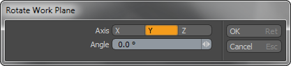
Axis: This option defines around which axis the Work Plane will rotate, originating at the Work Plane origin (0,0,0) position.
Angle: Defines the number of degrees to rotate the Work Plane away from its home position.
The Offset Work Plane function provides users a means to accurately position the Work Plane by way of an offset from its current position. Invoking the command opens this dialog pop up-
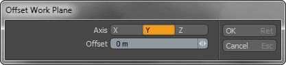
Axis: This option defines around which axis the Work Plane offset its position along.
Offset: Defines the distance to offset the Work Plan away from its current position.
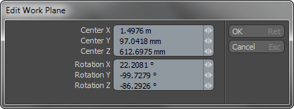
Displays the current values of the work plane as offset from the true world origin position at 0,0,0. Users can edit the values to precisely position and rotate the Work Plane.
This toggle will enable/disable the drawing of an axes handle widget in the viewport at the origin position of the Work Plane making it easier to recognize the center and axis directions.

