Particle Modifiers, or Pmods for short, offer way for users to modify particles in different and interesting ways. The 'Basic' modifier applied simple uniform transform controls for particles, where the 'Random' modifier applies the same thing but randomly. The 'Step' modifier applied stepped transforms based on the particles ID value, useful when applied to Point Clouds, but not limited to just them. The 'Sieve' modifier acts as a conditional controller, modifying particles based on user defined criteria. The 'Expression' modifier provides an extremely powerful means to modify particles procedurally and the 'Look At' modifier makes it easy to have the particles point toward specific items. Select from any of the Modifiers below to see the documentation related to them-
Particle Basic Modifier
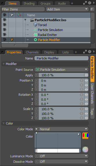
The 'Particle Modifier' will apply any or all of the three basic transforms (Move, Scale and Rotate) to a procedurally generated particle source, providing users a means to animate the final elements in interesting ways. The Basic particle modifier is applied as the go-between for any items 'Point Source' offering interesting ways of animating the resulting items.
The basic 'Particle Modifier' is a controller to apply simple transforms to particles, such as translate, rotate and scale. By itself, it doesn't offer any compelling benefits that can't be applied by the particle generators. However, when combined with 'Falloffs' and 'Particle Operators', some really interesting effects can be created. Such as particle rotation within the confines of a Falloff, or particles scaling when a collision is encountered.
Adding a Particle Modifier
Users can add a Particle Modifier item simply by using the 'Add Item' function of the Items List. LMB+click on the button to open the menu, then select the "Particles > Modifiers > Particle Modifier" option. Once added, users then need to specify the Point Source that they wish to affect. Once the originating point source is defined, users will also need to specify the 'Particle Modifier' item as the source in the final item. If thought of like a chain, the originating particle generation is defined as the source in the Modifier, and then the modified values are fed into the final effect, such as a Replicator, Blob, Volume or Sprite. The Source must be defined in this order so as to produce the intended result.
When applying the Basic modifier to an active particle simulation, users will need to connect the modifier in the proper order within the Schematic view. This can be done for existing networks by simply selecting the connector between the Simulation Item and the target and adding the modifier. The Basic modifier is found in the Schematic view in the 'Add...' menu under "Particles > Modifiers > Particle Modifier". When selected the following attributes are available in the 'Properties' panel-
 Name: This data field displays the current items name. Users may easily change it by LMB-clicking within the field and typing the new name.
Modifier--
Point Source: Defines the source of the particles that will be affected by the modifier.
Apply: The 'Apply' option acts as a multiplier, controlling the overall strength of the transforms applied to the source particles.
Position X/Y/Z: Determines a Position value for each individual axis as an offset from the particles originating position.
Rotation X/Y/Z: Determines a Rotation value for each individual axis as an offset from the particles originating orientation.
Scale X/Y/Z: Determines a Scaling value for each individual axis as an increase/decrease from the particles initial size.
Color--
The 'Color' options allow users to use mini gradient editors to assign and control different attributes for the resulting particles. These attributes are then passed along to the final effect, working with both 'Volumes and 'Sprites' . The gradient values are generated sequentially, dividing the gradient itself into the number of generated particles it is assigned to, each receiving the value for that position along the gradient. For example, a red to blue gradient assigned to a linear array of particles would produce one red particle at the start. The particle colors would then fade toward the blue color in even increments along the length of the array.
There are three different settings that can be applied to their associated surface attributes. Any of these functions are enabled by selecting any option other than 'Off' (the default value that disabled the function). The 'Mode' that is selected determines the way the blending of the gradient with the base setting of the target element.
Color Mode: The 'Color Mode' determines how the resulting gradient applies, defining the blending mode of the colors as they apply to the base particle coloring. The 'Color' Gradient Editor that opens will allow the user to define the actual gradient values that will be applied.
Luminance Mode: The 'Luminance Mode' determines how the resulting gradient applies, defining the blending mode of the Luminosity value as it applies to the base particle luminosity. The 'Luminosity' Gradient Editor that opens will allow the user to define the actual gradient values that will be applied.
Dissolve Mode: The 'Dissolve Mode' determines how the resulting gradient applies, defining the blending mode of the colors as they apply to the base particle transparency. The 'Dissolve' Gradient Editor that opens will allow the user to define the actual gradient values that will be determine the transparent amount.
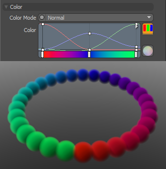
A 'Normal' Color Mode gradient applied to a 'Particle Generator's' radial array
Particle Random Modifier
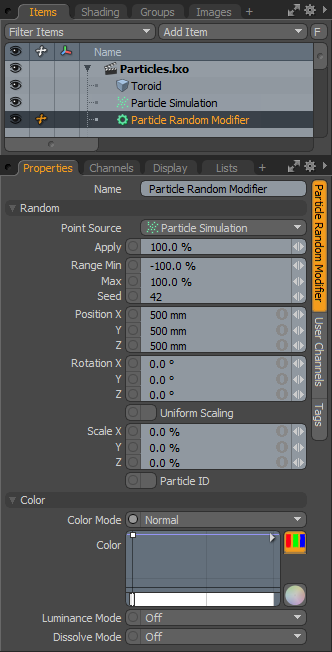
The 'Random Particle Modifier' will randomly apply any or all of the three basic transforms (Move, Scale and Rotate) to a procedurally generated particle source. The Random Particle Modifier is applied as the go-between for any items Point Source providing and easy way to add natural variations to the resulting particles. Interesting effects can also be created when combined with 'Falloffs' and 'Particle Operators'.
Adding a Particle Modifier
Users can add a Random Particle Modifier item simply by using the 'Add Item' function of the Items List. LMB+click on the button to open the menu, then select the "Particles > Particle Modifiers > Particle Random Modifier" option. Once added, users then need to specify the Point Source that they wish to affect. Once the originating point source is defined, users will also need to specify the 'Particle Modifier' item as the source in the final item. If thought of like a chain, the originating particle generation is defined as the source in the Modifier, and then the modified values are fed into the final effect, such as a Replicator, Blob, Volume or Sprite. The Source must be defined in this order so as to produce the intended result.
When applying the Random modifier to an active particle simulation, users will need to connect the modifier in the proper order within the Schematic view. This can be done for existing networks by simply selecting the connector between the Simulation Item and the target and adding the modifier. The Random modifier is found in the Schematic view in the 'Add...' menu under "Particles > Modifiers > Particle Random Modifier". When selected the following attributes are available in the 'Properties' panel-
 Name: This data field displays the current items name. Users may easily change it by LMB-clicking within the field and typing the new name.
Random--
Point Source: Defines the source of the particles that will be affected by the expression modifier.
Apply: Determines the overall degree that the expression affects the target. At 0% the target wouldn't be affected at all, attenuating up to 100% where the target is fully affected. This allows users to transition to the modified state.
Range Min/Max: The Range determines the amount of transform applied to the target over the entire range of the particles acting as a multiplier on the value. For example- If the Scale is set to 200% on all three axes, and the Range Min/Max is -100%/100% respectively, then the first particle would be Scaled -200% attenuating the value toward the last particle Scaled at 200%. The range is determined in the order of the Particle ID.
Seed: The 'Seed' value is the initial number used when generating the random procedural values. Different 'Seed' values will produce different random variations and can be useful in changing the result.
Position X/Y/Z: Defines the Position values added to the target for each axes.
Rotation X/Y/Z: Defines the Rotation values added to the target for each axes.
Uniform Scaling: When enabled, the random scaling factor is applied evenly on all axes.
Scale X/Y/Z: Defines the Scale values added to the target for each axes.
Particle ID: When the 'Particle ID' option is enabled, the unique ID identifier values will be randomized, instead of sequential of the initial particle.
Color--
The 'Color' options allow users to use mini gradient editors to assign and control different attributes for the resulting particles. These attributes are then passed along to the final effect, working with both 'Volumes and 'Sprites' . The gradient values are generated sequentially, dividing the gradient itself into the number of generated particles it is assigned to, each receiving the value for that position along the gradient. For example, a red to blue gradient assigned to a linear array of particles would produce one red particle at the start. The particle colors would then fade toward the blue color in even increments along the length of the array.
There are three different settings that can be applied to their associated surface attributes. Any of these functions are enabled by selecting any option other than 'Off' (the default value that disabled the function). The 'Mode' that is selected determines the way the blending of the gradient with the base setting of the target element.
Color Mode: The 'Color Mode' determines how the resulting gradient applies, defining the blending mode of the colors as they apply to the base particle coloring. The 'Color' Gradient Editor that opens will allow the user to define the actual gradient values that will be applied.
Luminance Mode: The 'Luminance Mode' determines how the resulting gradient applies, defining the blending mode of the Luminosity value as it applies to the base particle luminosity. The 'Luminosity' Gradient Editor that opens will allow the user to define the actual gradient values that will be applied.
Dissolve Mode: The 'Dissolve Mode' determines how the resulting gradient applies, defining the blending mode of the colors as they apply to the base particle transparency. The 'Dissolve' Gradient Editor that opens will allow the user to define the actual gradient values that will be determine the transparent amount.
A 'Normal' Color Mode gradient applied to a 'Particle Generator's' radial array
Particle Step Modifier
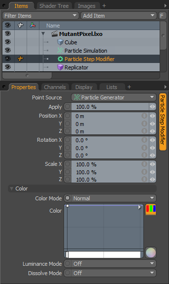
The 'Particle Step Modifier' will apply any or all of the three basic transforms (Move, Scale and Rotate) to a procedurally generated particle source, in additive steps. Meaning each subsequent element will inherit the transform of its predecessor and then apply the transform again, generating progressively positioned, scaled or rotated elements. The resulting affect on the particles is based on point order, so the transforms will be applied in that order. Generally meant for use with the 'Particle Generator', they can also be applied to the 'Particle Cloud' and the 'Surface Particle Generator' items.
Adding a Particle Modifier
Users can add a Particle Step Modifier item simply by using the 'Add Item' function of the Items List. LMB+click on the button to open the menu, then select the "Particles > Particle Step Modifier" option. Once added, users then need to specify the Point Source that they wish to affect. Once the originating point source is defined, users will also need to specify the 'Particle Step Modifier' item as the source in the final item. If thought of like a chain, the originating particle generation is defined as the source in the Step Modifier, and then the modified values are fed into the final effect, such as a Replicator, Blob, Volume or Sprite. The Source must be defined in this order so as to produce the intended result.
When applying the Step modifier to an active particle simulation, users will need to connect the modifier in the proper order within the Schematic view. This can be done for existing networks by simply selecting the connector between the Simulation Item and the target and adding the modifier. The Step is found in the Schematic view in the 'Add...' menu under "Particles > Modifiers > Particle Step Modifier". When selected the following attributes are available in the 'Properties' panel-
 Point Source: Defines the source of the particles that will be affected by the expression modifier.
Apply: The 'Apply' option acts as a multiplier, controlling the overall strength of the transforms applied to the original particles.
Position X/Y/Z: Determines a Position offset value for the initial particle for each individual axis. Subsequent particles will inherit this values and then apply it again, producing a stepped or progressive type effect.
Rotation X/Y/Z: Determines a Rotation offset value for the initial particle for each individual axis. Subsequent particles will inherit this values and then apply it again, producing a stepped or progressive type effect.
Scale X/Y/Z: Determines a Size increase/decrease for the initial particle for each individual axis. Subsequent particles will inherit this values and then apply it again, producing a stepped or progressive type effect.
Color--
The 'Color' options allow users to use mini gradient editors to assign and control different attributes for the resulting particles. These attributes are then passed along to the final effect, working with both 'Volumes and 'Sprites' . The gradient values are generated sequentially, dividing the gradient itself into the number of generated particles it is assigned to, each receiving the value for that position along the gradient. For example, a red to blue gradient assigned to a linear array of particles would produce one red particle at the start. The particle colors would then fade toward the blue color in even increments along the length of the array.
There are three different settings that can be applied to their associated surface attributes. Any of these functions are enabled by selecting any option other than 'Off' (the default value that disabled the function). The 'Mode' that is selected determines the way the blending of the gradient with the base setting of the target element.
Color Mode: The 'Color Mode' determines how the resulting gradient applies, defining the blending mode of the colors as they apply to the base particle coloring. The 'Color' Gradient Editor that opens will allow the user to define the actual gradient values that will be applied.
Luminance Mode: The 'Luminance Mode' determines how the resulting gradient applies, defining the blending mode of the Luminosity value as it applies to the base particle luminosity. The 'Luminosity' Gradient Editor that opens will allow the user to define the actual gradient values that will be applied.
Dissolve Mode: The 'Dissolve Mode' determines how the resulting gradient applies, defining the blending mode of the colors as they apply to the base particle transparency. The 'Dissolve' Gradient Editor that opens will allow the user to define the actual gradient values that will be determine the transparent amount.
A 'Normal' Color Mode gradient applied to a 'Particle Generator's' radial array
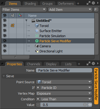
Particle Sieve Modifier
The Sieve Particle Modifier is a conditional filter that allows users to adjust values based on certain specified criteria. Only values that meet the defined criteria are passed along to the output (it doesn't modify the initial point source itself!). It is useful in filtering particles based on age, particle ID or a multitude of other options. IT can also be equally useful for Point Clouds; when combined with a Surface Particle Generator particles can be filtered by slope.
Adding a Particle Modifier
Users can add a Particle Sieve Modifier item simply by using the 'Add Item' function of the Items List. LMB+click on the button to open the menu, then select the "Particles > Particle Sieve Modifier" option. Once added, users then need to specify the Point Source that they wish to affect. Once the originating point source is defined, users will also need to specify the 'Particle Step Modifier' item as the source in the final item. If thought of like a chain, the originating particle generation is defined as the source in the Step Modifier, and then the modified values are fed into the final effect, such as a Replicator, Blob, Volume or Sprite. The Source must be defined in this order so as to produce the intended result.
When applying the Sieve modifier to an active particle simulation, users will need to connect the modifier in the proper order within the Schematic view. This can be done for existing networks by simply selecting the connector between the Simulation Item and the target and adding the modifier. The Sieve is found in the Schematic view in the 'Add...' menu under "Particles > Modifiers > Particle Sieve Modifier". When selected the following attributes are available in the 'Properties' panel-
 Name: This data field displays the current items name. Users may easily change it by LMB-clicking within the field and typing the new name.
Sieve--
Point Source: Defines the source of the particles that will be affected by the expression modifier.
If: The 'If' option controls which aspect of the Source particles will be evaluated for the defined condition. The Popup menu allows users to choose from one of the many options available.
Vertex Map: When the 'Point Sources is a Mesh item, users can define an associated 'Weight' vertex map, adding finer control to the Sieve. Those vertices with weight values greater than 0.0 are assumed to have a value of 1, vertices with weight value of less than 0.0, the value will be assumed to be 0 (basically it is a binary on or off behavior).
Condition: Determines under what condition that particles will be filtered. This works in conjunction with the 'Value' option.
Value: Defines the specific filtering value based on the Condition option selected. Value varies dependent on the 'If' option. Take for instance if 'Slope' is defined then the 'Value' will relate to angle of degrees.
Particle Expression Modifier
The 'Particle Expression Modifier' allows users to apply expressions to particles. An Expression is a set of instructions that are represented like a mathematical formula. In the case of this 'Particle Expression Modifier', certain mathematical controls can be applied to particles to control various aspects of the particles motions or positions, or can assign a control when a certain condition is met. The expression itself controls the way in which the particles are affected, the 'Apply' and 'Range' options control the degree of its affect, and the transform options control the actual modification that is applied to the target.
Usage
The Particle expression modifier can be added to the scene using the 'Particles' submenu within the toolbox found in the 'Setup' interface. Users can also use the 'Add Items' function of the Items list, found under "Particles > Modifiers > Particle Expression Modifier". Once added to the scene, users will need to drag the item itself from the Items list and drop it in the Schematic viewport. The Expression Modifier is connected between the Point Source element and the point target items, such as a Replicator. The connection should look something like this-
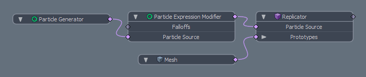
The Expression is modifying the particle values from the Source, which can be any number of particle items, either static or dynamic, but in this case is a simple Particle Generator. Those values are replaced with the Expression evaluations and then passed on to the target. The value returned by the expression are multiplied by the values set in the other channels of the Modifier. For example- if a user wanted a sine wave on the Y axis that moved through the range of the particles with time, the expression would be "sin(T+PID)". Where using 'PID' (Particle ID) is an offset to the current time applied to the Y position. Then we just need to set the 'Position Y' transform option to a positive value, such as 1m and all the other Pos, Rot and Scale channels to 0.0. When the timeline is played the sine 'wave' will transform the positions of the particles 1m modulating up and down with the default Range Min/Mas values of -100%/100% respectively.
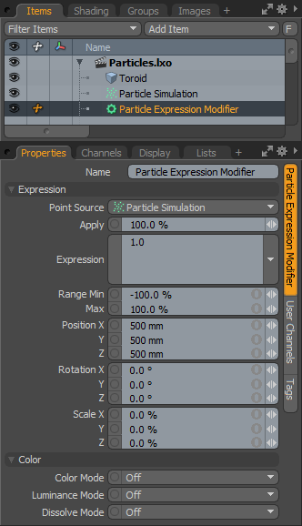
When the Particle Expression Modifier is selected the following attributes appear in the 'Properties' panel-
 Name: This data field displays the current items name. Users may easily change it by LMB-clicking within the field and typing the new name.
Expression--
Point Source: Defines the source of the particles that will be affected by the expression modifier.
Apply: Determines the overall degree that the expression affects the target. At 0% the target wouldn't be affected at all, attenuating up to 100% where the target is fully affected. This allows users to transition to the modified state.
Formula: This is where the actual expression formula is entered.
Range Min/Max: The Range determines the amount of transform applied to the target over the entire range of the particles acting as a multiplier on the value. For example- If the Scale is set to 200% on all three axes, and the Range Min/Max is -100%/100% respectively, then the first particle would be Scaled -200% attenuating the value toward the last particle Scaled at 200%. The range is determined in the order of the Particle ID.
Position X/Y/Z: Defines the Position values added to the target for each axes.
Rotation X/Y/Z: Defines the Rotation values added to the target for each axes.
Scale X/Y/Z: Defines the Scale values added to the target for each axes.
Color--
The 'Color' options allow users to use mini gradient editors to assign and control different attributes for the resulting particles. These attributes are then passed along to the final effect, working with both 'Volumes and 'Sprites' . The gradient values are generated sequentially, dividing the gradient itself into the number of generated particles it is assigned to, each receiving the value for that position along the gradient. For example, a red to blue gradient assigned to a linear array of particles would produce one red particle at the start. The particle colors would then fade toward the blue color in even increments along the length of the array.
There are three different settings that can be applied to their associated surface attributes. Any of these functions are enabled by selecting any option other than 'Off' (the default value that disabled the function). The 'Mode' that is selected determines the way the blending of the gradient with the base setting of the target element.
Color Mode: The 'Color Mode' determines how the resulting gradient applies, defining the blending mode of the colors as they apply to the base particle coloring. The 'Color' Gradient Editor that opens will allow the user to define the actual gradient values that will be applied.
Luminance Mode: The 'Luminance Mode' determines how the resulting gradient applies, defining the blending mode of the Luminosity value as it applies to the base particle luminosity. The 'Luminosity' Gradient Editor that opens will allow the user to define the actual gradient values that will be applied.
Dissolve Mode: The 'Dissolve Mode' determines how the resulting gradient applies, defining the blending mode of the colors as they apply to the base particle transparency. The 'Dissolve' Gradient Editor that opens will allow the user to define the actual gradient values that will be determine the transparent amount.
Particle Variables--
The following table lists per-particle variables supported by the parser. Note that for 'AGE', 'PATH', and 'MASS' you will need to enable these features on the 'Particle Simulation' item otherwise they will return zero. User channels can be reference by name in the expression.
| Variable
|
| Meaning
|
| PX, PY, PZ
|
| Position
for X, Y & Z
|
| PPX, PPY, PPZ
|
| Previous Position
for X, Y & Z
|
| RX, RY, RZ
|
| Rotation
for X, Y & Z
|
| SX, SY, SZ
|
| Scale
for X, Y & Z
|
| VX, VY, VZ
|
| Velocity
for X, Y & Z
|
| FX, FY, FZ
|
| Force
for X, Y & Z
|
| CR, CG, CB
|
| Color
for R, G & B
|
| LUM
|
| Luminance
|
| PID
|
| Particle ID
|
| PCNT
|
| Particle Count
|
| AGE
|
| Particle Age
|
| MASS
|
| Particle Mass
|
| SIZE
|
| Particle Size
|
| PATH
|
| The distance the particle has traveled
|
| DISS
|
| Dissolve
|
| RATE
|
| Rate
|
| ITEM
|
| Item
|
| T
|
| Time
|
Built-in Function--
The following table gives an overview of the functions supported by the default implementation. It lists the function names, the number of arguments and a brief description.
| Name
|
| Meaning
|
| sin
|
| sine function
|
| cos
|
| cosine function
|
| tan
|
| tangens function
|
| asin
|
| arcus sine function
|
| acos
|
| arcus cosine function
|
| atan
|
| arcus tangens function
|
| sinh
|
| hyperbolic sine function
|
| cosh
|
| hyperbolic cosine
|
| tanh
|
| hyperbolic tangens function
|
| asinh
|
| hyperbolic arcus sine function
|
| acosh
|
| hyperbolic arcus tangens function
|
| atanh
|
| hyperbolic arcur tangens function
|
| log2
|
| logarithm to the base 2
|
| log10
|
| logarithm to the base 10
|
| log
|
| logarithm to the base 10
|
| ln
|
| logarithm to base e (2.71828...)
|
| exp
|
| e raised to the power of x
|
| sqrt
|
| square root of a value
|
| sign
|
| sign function -1 if x<0; 1 if x>0
|
| rint
|
| round to nearest integer
|
| abs
|
| absolute value
|
| min
|
| min of all arguments
|
| max
|
| max of all arguments
|
| sum
|
| sum of all arguments
|
| avg
|
| mean value of all arguments
|
Built-in Binary Operators
The following table lists the default binary operators supported by the parser.
| Operator
|
| Meaning
| Priority
|
| =
|
| assignment
*
| -1
|
| &&
|
| logical and
| 1
|
| ||
|
| logical or
| 2
|
| <=
|
| less or equal
| 4
|
| >=
|
| greater or equal
| 4
|
| !=
|
| not equal
| 4
|
| ==
|
| equal
| 4
|
| >
|
| greater than
| 4
|
| <
|
| less than
| 4
|
| +
|
| addition
| 5
|
| -
|
| subtraction
| 5
|
| *
|
| multiplication
| 6
|
| /
|
| division
| 6
|
| ^
|
| raise x to the power of y
| 7
|
Other Operators
muParser has built in support for the if/then/else operator. It uses 'lazy' evaluation in order to make sure only the necessary branch of the expression is evaluated.
| Operator
| Meaning
| Remarks
|
| ?:
| if then else operator
| C/C++ style syntax
|
Particle Look At Modifier
The 'Particle Look At Modifier' will orient the Z+ direction of the source particles toward a user-defined target item. The target item can be static or animated. When animated the source particles rotation values will be adjusted so that it always remains oriented toward the target.
Adding a Particle Modifier
Users can add a Particle Look At Modifier item simply by using the 'Add Item' function of the Items List. LMB+click on the button to open the menu, then select the "Particles > Particle Step Modifier" option. Once added, users then need to specify the Point Source that they wish to affect. Once the originating point source is defined, users will also need to specify the 'Particle Step Modifier' item as the source in the final item. If thought of like a chain, the originating particle generation is defined as the source in the Step Modifier, and then the modified values are fed into the final effect, such as a Replicator, Blob, Volume or Sprite. The Source must be defined in this order so as to produce the intended result.
When applying the Look At modifier to an active particle simulation, users will need to connect the modifier in the proper order within the Schematic view. This can be done for existing networks by simply selecting the connector between the Simulation Item and the target and adding the modifier. The Sieve is found in the Schematic view in the 'Add...' menu under "Particles > Modifiers > Particle Look At Modifier". When selected the following attributes are available in the 'Properties' panel-
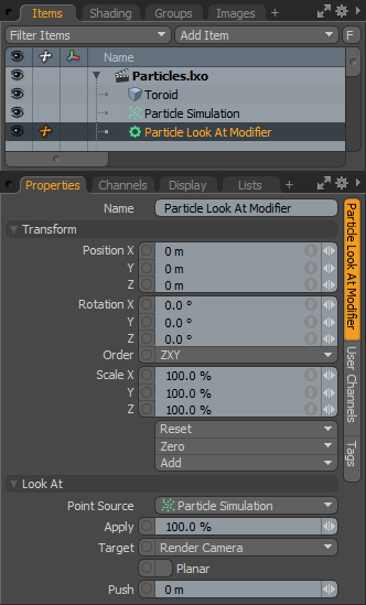 Name: This data field displays the current items name. Users may easily change it by LMB-clicking within the field and typing the new name.
Transform: When using the 'Target' option 'This Locator', the 'Position XYZ' values control the location of the Look At modifiers Locator item in the scene, which defines the position that the targeted elements will orient towards.
Look At--
Point Source: Defines the source of the particles that will be affected by the expression modifier.
Apply: The 'Apply' option acts as a multiplier, controlling the overall strength of the transforms applied to the original particles.
Target: Defines which item in the scene the source will orient toward. Option include-
This Locator- Orients toward the Locator item of the Look At modifier itself.
Next/Previous Particle- Each Particle in a given simulation or cloud is given a unique ID value in the order the particles are generated. The Next or Previous options can create chain or snaking type effects where particles orient toward earlier or later particles.
Render Camera- Orients towards whatever camera is selected as the 'Render Camera' in the Render item.
Planar: When 'Planar' is enabled, items will only rotate around the 'UP' axis, especially useful for billboard style image planes (flat polygons with a transparent images mapped onto it).
Push: The 'Push' control is an offset determines by the angle between the target and the actual particle location. Positive values push the target items further from the defined Target, and negative values bring them closer.
Particle Audio Modifier
The 'Particle Audio Modifier' uses the frequency response of an imported audio file to modify any (or all) of the three basic item transforms (Move, Scale and Rotate) when assigned to a particle source. This provides users a means to animate the final elements in unique and interesting ways, that synchronize to the music. The way it works is by dividing the audio spectrum into the same number of 'samples' as the number of particles. At each designated sample location the amount of audio variance is converted to a percentage and applied the the desired transform channel.
Usage
Users can add the Audio Particle Modifier item simply by using the 'Add Item' function of the Items List. LMB+click on the button to open the menu, then select the "Particles > Modifiers > Particle Audio Modifier" option. Next users will need to connect the modifier to a point source and specify the audio file, this is best accomplished in the Schematic viewport.
Once added, users then need to specify the 'Point Source' that they wish to affect. Once the originating point source is defined, users will also need to specify the 'Particle Modifier' item as the source in the final item. If thought of like a chain, the originating particle generation is defined as the source in the Modifier, and then the modified values are fed into the final effect, such as a Replicator, Blob, Volume or Sprite. The Source must be defined in this order so as to produce the intended result.
When applying the Audio modifier to an active particle simulation, users will need to connect the modifier in the proper order within the Schematic view. This can be done for existing networks by simply selecting the connector between the Simulation Item and the target and adding the modifier. The Audio modifier is found in the Schematic view in the 'Add...' menu under "Particles > Modifiers > Particle Audio Modifier". When selected the following attributes are available in the 'Properties' panel-
 Name: This data field displays the current items name. Users may easily change it by LMB-clicking within the field and typing the new name.
Modifier--
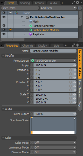
Point Source: Defines the source of the particles that will be affected by the modifier.
Apply: The 'Apply' option acts as a multiplier, controlling the overall strength of the transforms applied to the source particles.
Position X/Y/Z: Determines a Position value for each individual axis as an offset from the particles originating position.
Rotation X/Y/Z: Determines a Rotation value for each individual axis as an offset from the particles originating orientation.
Scale X/Y/Z: Determines a Scaling value for each individual axis as an increase/decrease from the particles initial size.
Audio--
Lower Cutoff: The Lower Cutoff defines a minimum threshold in the frequency range where anything below the defined threshold will be ignored. This is useful to eliminate some slight motion that might appear in a noisy audio file.
Spectrum Scale: The 'Spectrum Scale' is a multiplier that determines the influence of a given frequency. Lower frequencies are on the left of the gradient and higher ones to the right. This can also be used as a virtual crossover to completely cut out certain frequency ranges, for example the audio is driving a woofer animation a key can be added to cut out all of the high end.
Color--
The 'Color' options allow users to use mini gradient editors to assign and control different attributes for the resulting particles. These attributes are then passed along to the final effect, working with both 'Volumes and 'Sprites' . The gradient values are generated sequentially, dividing the gradient itself into the number of generated particles it is assigned to, each receiving the value for that position along the gradient. For example, a red to blue gradient assigned to a linear array of particles would produce one red particle at the start. The particle colors would then fade toward the blue color in even increments along the length of the array.
There are three different settings that can be applied to their associated surface attributes. Any of these functions are enabled by selecting any option other than 'Off' (the default value that disabled the function). The 'Mode' that is selected determines the way the blending of the gradient with the base setting of the target element.
Color Mode: The 'Color Mode' determines how the resulting gradient applies, defining the blending mode of the colors as they apply to the base particle coloring. The 'Color' Gradient Editor that opens will allow the user to define the actual gradient values that will be applied.
Luminance Mode: The 'Luminance Mode' determines how the resulting gradient applies, defining the blending mode of the Luminosity value as it applies to the base particle luminosity. The 'Luminosity' Gradient Editor that opens will allow the user to define the actual gradient values that will be applied.
Dissolve Mode: The 'Dissolve Mode' determines how the resulting gradient applies, defining the blending mode of the colors as they apply to the base particle transparency. The 'Dissolve' Gradient Editor that opens will allow the user to define the actual gradient values that will be determine the transparent amount.
A 'Normal' Color Mode gradient applied to a 'Particle Generator's' radial array
Top