
In order for any item in MODO to be evaluated in a Dynamics simulation, it must first be converted to a dynamic item. This is done by tagging it appropriately. The controls to apply the tagging are found in the toolbox of the 'Setup' interface layout under the 'Dynamics' subtab. The options include creating either a 'Active' 'Compound', 'Kinematic' or 'Static' Rigid Bodies, 'Soft Body' or 'Dynamic Curves' (for Fur Guides). To apply the tag, simply select the item(s) while in 'Items' mode and invoke the appropriate button in the interface. What tag is selected is dependent on the desired results, with each body type explained below (in the 'Type' options section of course). Once the appropriate tag is assigned, an additional property sub form called 'Dynamic' is added to the items 'Properties' panel with a series of attributes relating to the settings of the object and the dynamics simulation. While the default values will work in some cases, users will likely wish to modify the defaults to settings more appropriate for their intended purpose.
To make an object un-dynamic, removing it completely from the Dynamics evaluations, users simply need to select the target item and invoke the menu bar command "Dynamics > Make Un-dynamic" eliminating any dynamics information from the object. To temporarily disable the object from the dynamics simulation, toggle the 'Enable' option. When any Dynamic item is selected, the following attributes appear in the 'Properties' panel-
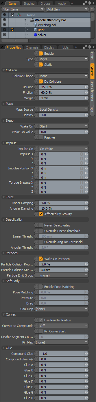 Enable: Toggles dynamics on and off for the item. When enabled, MODO will calculate dynamics for the item when a simulation is run or cached. When disabled, the dynamic properties will be ignored.
Type: Dynamic items can be defined to be one of three types- 'Rigid', 'Softbody' or 'Curves'. Each with its own set of controls and attributes--
Rigid: When the 'Rigid' option is selected, the item will be treated as a solid object with a fixed, unchanging volume. Rigid elements have three possible states. When the 'Static' toggle is enabled, the associated item will not move during a simulation (even if animated!), acting strictly as a collision shape. When 'Static' is disabled, the two additional options become available in a 'State' menu-
Dynamic- These are collision items that are controlled exclusively by Dynamics. It can also be affected by Constraints, Forces and Falloffs. This is the state option automatically designated when an object is defined as an 'Active Rigid Body'.
Kinematic- An animated collision object that is controlled by keyframe information. Kinematic objects are unaffected by Forces, such as gravity or Falloffs. This is the option automatically designated when an object is defined as a 'Kinematic Rigid Body'.
Softbody: Softbodies are are a special type of object that deform when a collision is calculated or a Force is applied. This is the option is automatically assigned when an object is defined as an 'Softbody' using the button in the UI.
The shape of the resulting Softbody is determined by virtual springs evaluated between the vertices in the mesh. There are three different arrangements to the springs that have different influences over the shape deformation- 'Stiffness Bend', 'Struct' (structure) and 'Sheer'. These three additional options only appear when an item is designated as a Softbody.
Stiffness Bend- These springs help an object maintain it's shape by applying a rotational force to maintain the continuity of the surface. The default of 0.5 makes a fairly rigid, almost rubber-like surface. Stiffness can be reduced all the way to 0 creating a very soft and saggy fabric type of result.
Struct- These springs follow along the lines of the mesh (along the polygon edges) and determines how resistant to the applied forces the springs are when deforming (such as Gravity or Turbulence).
Sheer- These springs are generated that add extra connections to the inside of a polygon face (quad polygons forming an x shape) These springs help prevent the polygon from collapsing in on itself.
Number of Clusters- This is basically the resolution of the Soft Body collision geometry. The higher the number the more accurate the soft body will look. This does nothing to affect the ability of the Soft Body to actually collide, but rather controls the size of the internally created collision object used to test collisions. Setting this number to 0 will turn off all collisions for the Soft Body, while setting it to -1 will try to create a collision object per-face. Regardless of the setting, the maximum number of clusters is 8192. Note that increasing the number of clusters can significantly increase simulation time.
Curves: When the 'Curves' option is selected users will be able to apply simulations to various Curve types in MODO, both 'Spline' and 'Polylines' (Fur Guides). The simulations of curves are very much like the rigid body calculations, simulating a connected string of rigid capsule shapes, drawn between each vertex, with their sizing based on the 'Curve Radius' value in the Mesh item properties. The resulting capsule collision shapes have three possible states for dynamics. When the 'Static' toggle is enabled, the associated curves will not move during a simulation (even if animated!), acting strictly as collision shapes. When 'Static' is disabled, the two additional options become available in a 'State' menu-
Dynamic- These are collision items that are controlled exclusively by Dynamics. This is the setting for users animating fur guides. Dynamic curves will also be affected by Forces and Falloffs, as well as motions introduced by the influence of other deformers (e.g. animated characters).
Kinematic- An animated collision object that is controlled by keyframe information. Kinematic objects are unaffected by Forces, such as gravity or Falloffs.
Collision--
Collisions define the underlying shape used in a simulation to calculate contact between dynamic elements. Simulations that fail often do so because of incorrect collision settings so it is important to make sure they are properly defined. There are three possible states for the collision settings, providing unique attributes for 'Rigid', 'Softbody and for 'Curves'.
Collision (Rigid)--
Collision Shape: This setting defines the shape that will be used to calculate collision contacts between dynamic objects. Generally users will want to choose the simplest shape that produces satisfactory results. The default collision shape is set to 'Hull' which generally balances accuracy with calculation speed.
Box- A rectangular box defined by the bounding box of the geometry's maximum extents.
Sphere- A sphere that is sized to encompass all the geometry of the object.
Hull- The default collision option 'Hull' creates the smallest convex volume that encompasses all the points in this mesh. To visualize it, imagine the mesh enveloped in shrink-wrap. The 'Hull' collision type does not support holes or indentations in the object. While only approximating the items shape, it will provide very fast collision detection on complex shaped objects.
Mesh- Uses the actual mesh of the object for calculating collisions. For Subdivision Surfaces models, the actual frozen SubD cage is used. This option should be avoided on 'Dynamic' Rigid Bodies (it is OK for 'Static' and 'Kinematic'). When used otherwise performance, as well as simulation stability can suffer negatively.
Convex Decomposition- The 'Convex Decomposition' creates multiple Hulls (described above) and connects them together. This works to better approximate the actual shape of the geometry but can be costly to initially compute on complex shapes.
Plane- Generates a infinite ground plane collision shape originating from the center of the associated geometry's bounding box (not on the items actual 'center' position).
Do Collisions: Users can disable this option so that the object is not taken in to account for collision calculations (enabled by default).
Bounce: This is the collision response when this object hits another dynamic object. A value of 0% means the object will not bounce or inherit energy from other dynamic objects it contacts. A value of 100% would inherit all of the energy from the contact object. Values above 100% will produce rubber-ball like effects where objects impart more energy from contacts
Friction: The amount an object will slide against another object. A value of 0.0 would offer no resistance, while a value of 1.0 would keep the object from sliding entirely.
Margin: The 'Margin' value helps the bullet engine to better determine collisions, as well as improves its performance and reliability. The 'Margin' value defines a gap around the object used to detect a collision contact. In most cases it should be kept at its default value. When used with the 'Mesh' and 'Convex Decomposition' settings this can offset items away from each other, so only a small amount is necessary. Note that a setting of '0' (zero) may produce errors in collision detection.
Collision (Softbody)--
Friction: The amount that a Softbody will slide against another dynamic object. A value of 0.0 would offer no resistance, while a value of 1.0 would keep the object from sliding entirely.
Margin: The 'Margin' value helps the bullet engine to better determine collisions, as well as improves its performance and reliability. The 'Margin' value defines a gap around the object used to detect a collision contact. Note that a setting of '0' (zero) may produce errors in collision detection.
Collision (Curves)--
Do Collisions: Users can disable this option so that the curves are not taken in to account for collision calculations (enabled by default).
Bounce: This is the collision response when the curve capsule colliders hit another dynamic object. A value of 0% means the object will not bounce or inherit energy from other dynamic objects it contacts. A value of 100% would inherit all of the energy from the contact object. Values above 100% will produce rubber-ball like effects where objects impart more energy from contacts
Friction: The amount an object will slide against another object. A value of 0.0 would offer no resistance, while a value of 1.0 would keep the object from sliding entirely.
Mass--
Mass Source: When the 'Mass Source' is set as 'World Density', the mass of an object is calculated by multiplying the calculated volume of the dynamic item by the 'Global Density' value defined on the Dynamics Solver item. Users can override that value by setting the 'Mass Source' to 'Local Density' or 'Local Mass' and expressly setting a value.
Density: Density is the measure of the amount of matter in any given volume. If the 'Mass Source' option is set to 'Local Density', this is the density value that will be used. The mass of the object will be determined by multiplying the computed volume by this value.
Mass: Mass is the properties of an object that give it bulk and weight. It is essentially a different way of determining density. If 'Mass Source' is set to 'Local Mass', this is the value that will be used for simulations.
Wake On: Normally objects are awake (active) when any dynamic simulation starts and the object begins to react immediately. Users can change this behavior delaying when individual objects wake up and become active, essentially controlling when items will begin their participation in a simulation. Prior to the 'Wake On' event, items can be keyframe animated and the object will be handed off to Dynamics for simulation when the certain 'Wake On Value' threshold is achieved. The values defined in the 'Impulse' channels are applied when the object wakes up.
Start- Object begins the dynamic simulation awake and fully active at the beginning of the scene.
Collision Velocity- Object wakes up when either another passive or active object collides with it. Users can use the 'Wake On Value' to set a collision velocity threshold necessary to wake up the object.
Collision Force- Object wakes up when either another passive or dynamic object collides with it. Users can use the 'Wake On Value' to set a collision force threshold necessary to wake up the object.
Velocity- Object wakes up when a certain velocity is reached. Different from 'Collision Velocity', this velocity is determined by keyframe animated motion. Users can use the 'Wake On Value' to set the velocity threshold necessary to wake up the object.
Trigger- Object wakes up when the keyframeable channel, 'reWakeOnValue' is non zero (any number but zero). This has good use with conditional nodes in rigging.
Frame- Object wakes up when a specific frame number is reached.
Time- Object Wakes Up when a specific time has been reached, regardless of frame-rate.
Wake On Value: Depending on the 'Wake On' option selected, users can set a threshold that must be reached in order to wake up the object.
Passive: When the 'Passive' option is enabled sleeping objects will react to collision forces only. This means they can be pushed around but will stop moving the moment the influence stops.
Impulse--
Impulse On: This option determine the state that causes the 'Impulse' value to be applied to the dynamic item-
Off- With this setting no Impulse value will be applied to the object.
On Wake- With this setting the Impulse values will be applied when the item wakes up, as determined by the 'Sleep' settings.
Continuous- With this setting the Impulse value will be applied to the object continually, at every time step in the evaluation.
Impulse X/Y/Z: A directional force that is applied to the object when it wakes up. Useful when a keyframed object is handed off to Dynamics, imparting direction and velocity to the object, which would otherwise just drop without it as Dynamics has no awareness of the objects velocity prior to waking up.
Impulse Position X/Y/Z: Position the above impulse is applied from affecting the objects trajectory.
Torque Impulse X/Y/Z: A rotational force that is applied to the object when it wakes up. Useful when a keyframed object is handed off to Dynamics, imparting rotation to the object, which would otherwise not spin without it as Dynamics has no awareness of the objects motion prior to waking up.
Force--
Linear Damping: This is a force that acts upon the motion of objects, acting to slow them down over time. A small value here can benefit object stability since it helps objects come to rest.
Angular Damping: Same as 'Linear Damping' but applies to the rotation of the object.
Affected by Gravity: Users can use this option to toggle on or off gravity's global influence for specific items.
Deactivation--
Never Deactivates: When this option is enabled, the item will never be deactivated due to no motion. When disabled, the item will be disabled when it meets the defined Linear and angular thresholds defined in the Solver item (or overridden here).
Override Linear Threshold: Users can enable this function to put dynamic objects to sleep once they reach a defined upper threshold value, overriding the Global value found in the Dynamics Solver. Essentially the opposite of the 'Wake On' settings, once an object has been below the threshold for the defined length of time, Dynamics puts it to sleep.
Linear Threshold: This is the motion threshold value when 'Override Linear Threshold' is enabled.
Override Angular Threshold: Users can enable this function to put dynamic objects to sleep once they reach a defined upper threshold value, overriding the Global value found in the Dynamics Solver. Essentially the opposite of the 'Wake On' settings, once an object has been below the threshold for the defined length of time, Dynamics puts it to sleep.
Angular Threshold: This is the rotation threshold value when 'Override Angular Threshold' is enabled.
Particles--
Wake On Particles: The 'Wake on Particles' can be enabled to determine interactions between dynamic items and particles. Necessary for 'Wake On' actions that are triggered by particle collisions.
Particle Collision Roughness: Adds a random factor to the direction particles bounce of this item. At 100% it can bounce up to 90 degrees away from the collision normal.
Particle Collision Stickiness: The distance at which particles will try to stick to the surface of this item.
Particle Emit Group: When a 'Particle Emit' Group' item is defined (either a 'Group' of dynamic items or a single other dynamic item), the dynamic item will emit a particle at the contact point when it collides with the defined item(s). This option requires an additional connection (in the Schematic viewport) to the Dynamic Collider item.
Softbody--
Enable Pose Matching: The 'Enable Pose Matching' option controls the Softbodies ability to go back to its original shape when deformed by dynamic forces (or other collision objects). Think of it like a rubber ball that is stepped on. This option enables the function, but the 'Pose Matching' percentage controls to what degree that original shape is obtained after the deformation is applied.
Pose Matching: When 'Enable Pose Matching is enabled, the 'Pose Matching percentage controls to what degree the softbody goes back to its original shape when deformed by outside forces.
Pressure: The 'Pressure' value exerts a force upon the overall volume of an item, similar to how pressure would react on an object in the real world, increasing values would add overall volume, inflating it and decreasing (negative) values would reduce its volume, deflating it. This option requires that the target mesh be completely watertight (no seams).
Drag: The 'Drag' option determines the loss of energy on a surface that is in motion (say for jiggling type of effects).
Goal Map: The 'Goal Map' is a Vertex Map that applies to Soft Body items and controls how much it retains its initial undeformed shape. It can also be looked at as a stiffness control. Weight Map values of 1.0 will retain the original undeformed position, while values lower than 1 will apply an appropriate spring force attempting to retain the initial shape.
Use Render Radius: When the 'Use Render Radius' option is enabled (the defaults state) the resulting capsules generated with dynamics will match the size defined, even when they are modulated with a curve width gradient.
Curves as Compounds: The 'Curves as Compounds' option controls the rigidity of the curves in a simulation as well as how multiple curves within a single item layer are treated with three different options-
Off- All curves are treated individually as soft, deforming elements.
Per Curve- All curves are treated individually as rigid, non-deforming elements.
Item- All curves are treated as a combined (single) rigid, non-deforming element.
Curve Radius: When the 'Use Render Radius' option is disabled, the 'Curve Radius option determines the collision size for the resulting capsule collision elements.
Pin Curve Start: The 'Pin Curve Start' when enabled will automatically pin the first vertex of a curve. Pinned vertices will remain fixed to their position within the mesh layer, moving only when the layer is animated or its geometry is deformed. This option is mainly used for simulating hair guides, to keep them connected to their character.
Disable Segment Collision Start: The collision capsules that are generated for a simulation are generated between each vertex, creating a chain of collision objects. The first segment begins at the base position of the curve. For pinned curves the first segment is always disabled for collision. The 'Disable Segment Collision Start' value allows users to the ability to disable collision on additional segments For example, a curve with 8 segments pinned to a character, if the 'Disabled Segment' value is specified at 3, then only the last 5 segments of the curve would be considered for collision.
Pin Map: The Pin Map allows users to specify specific vertices along the curve as fixed, meaning they wont move or be affected by the dynamics. This is done by the addition of a Pick Map. Pick Maps are specific type of vertex map that designates vertices as selected or not selected. Users can create a Pick Map using the Lists viewport and selecting the 'New Map' option under 'Other Maps'. In the dialog set the 'Vertex Map Type' as a 'Pick' map and define a unique name and press 'OK'. Next, in Vertices selection mode select the target vertices in the curve that should remain fixed. Making sure the new pick map is also selected, add the vertices to the Pick map, with the menu bar command "Vertex Map > Set Value..." and in the dialog, make sure that the 'Vertex Map Type' is set to 'Pick and then in 'Value' set a value of '1.0' and press OK. Now the Pick map is defined, then under the 'Pin Map' menu the 'Pick Map should be assigned, once designated as the 'Pin Map' the targeted vertices wont be affected by curve dynamics. Additional vertices can be added or removed from the Pick map at a later time by selecting them and then in the 'Set Value...' dialog a value of 0.0 means the vertex is not selected (affected by dynamics) and a value of 1.0 means it is selected (and will not be affected by dynamics).
Glue--
The 'Glue' option, as the name implies, is a function to connect opposing faces
during a simulation and only works for faces that are directly on top of each other, such as those between objects created using the 'Shatter' function, or say for stacked elements (like Bricks). The Glue function will hold the items together until they are met with the amount of force designated in the 'Glue' input fields, allowing them to then break apart into their individual items.
To use, each dynamic item must be a separate item in the Items list. The way it works then is that if the Items have touching, opposing faces, then the average of the highest 'Glue' value the neighboring items share is used to connect them. The 'Glue A' through 'Glue H' options allow a hierarchy of Glue strengths to be assigned, for the purposes of building additional structure between dynamic pieces, meaning they all won't shatter at the same time.
Take for instance this scenario, a brick wall that is flanked by two cement columns that will be destroyed by a wrecking ball. The bricks are stacked elements and the columns are diced up using the Shatter function. By selecting all the items and inputting a 'Glue A' amount of 1, then selecting all the pieces that make up just the columns and adding an additional 'Glue B' amount of 5. Now during the simulation there are three possible connections, the bricks that all share the 'Glue A' attribute, The pieces of the columns that share the 'Glue B' attributes and the connections between the bricks and columns that share a 'Glue A' attribute, but not a 'Glue B'.
When the wrecking ball hits the wall, the bricks should break apart easily as they all share the same 'Glue A' value, the bricks that touch the columns will also break away more easily since the bricks don't have the Glue B value that the pieces of the column share. The columns fall but remain somewhat intact because the initial force wasn't enough to break apart the Glue B connection. Having designated the additional B value overrides the A value, since neighboring items both share them. When the columns fall and hit the ground object, this collision imparts enough force to break them apart. So in this simulation the bricks broke more easily as would be expected, but it took more force to break the columns into their individual pieces. They retained their structure longer, but still broke apart during the same simulation.
Compound Glue: When working with 'Compound Rigid Bodies', the 'Compound Glue' option is used to connect the items within the same compound group. When the amount of force exceeds the designated amount the items will break apart from the compound and be treated as an individual item during a simulation. Note that only items that are physically touching each other (sharing some geometry) will be glued together, elements floating away from the compound group will not be affected by the 'Compound Glue' value.
Compound Glue +/- : This option allows users to add in some additional variance to the 'Compound Glue' amount. When a value is specified, the 'Compound Glue' setting will randomly vary within the range of the designated amount.
Glue A-H: The Glue A through H setting provide a hierarchy of Glue values that hold opposing items together. The highest alphanumeric setting with an assigned value above 0 that is shared between items will take precedence. If one item has an A value, but its neighbor has an A and B value, the B value will be ignored as the neighbors don't share the B setting. If one was only A and the other only B then they would not connect at all because they don't share any value. If both share a designation, but the value in the input fields are different, then the average setting of both fields is used instead.

