Constraints are basically joints, affecting the movement of dynamic objects in a scene, restricting their motion in very specific ways dependent on the type of constraint applied. Dynamics offers a variety of Constraint types providing users a means to produce very controlled dynamic simulations. Additionally, Constraints can be combined together (by way of Locators) producing even more control to complex dynamic simulations.
--Select from any of the Constraint types by clicking the title links below--
Using Constraints
Constraints in Dynamics are simply joints that connect two dynamic bodies together. Each constraint provides a different type of joint, limiting the motions of the dynamic objects in very specific ways. Typically constraints are used to relate the dynamic motion of an 'Active Rigid Body' item to that of a static or animated 'Passive Rigid Body' item. For instance, if a user wanted to animate a pair of dice swaying from the rear view mirror of a car, the car itself (including the mirror) would be defined as a 'Passive Rigid Body', and the pair of dice within would be defined as a 'Active Rigid Body'. Next the user would assign a 'Point' constraint to the mirror and the pair of dice and position it near the mirror. If the car were animated to move as if it was traveling over rough terrain, running a subsequent Dynamics simulation would then produce an incredibly realistic secondary swinging motion to the pair of dice without the need to add a single keyframe.
Constraints are also a powerful way to provide control of Active Dynamic objects, relating the motion of one to that of another. This is handled in the same way as the above example, but both items would be designated as 'Active Rigid Bodies'. Both objects would then move relative to the motions of the other, controlled by the constraint joint. Furthermore, series' of constraints can be added to consecutive objects, providing linked motions for the entire length of items. This is applied by selecting the chain of items in order and then applying the constraint.
Applying Constraints
Constraints can be added to scenes like any other item using the Items lists 'Add Item' function by first selecting the target items the user wishes to join together, and utilizing the various Constraint buttons found in the toolbox of the 'Setup' interface. When created, the constraint item will automatically link to the selected items. To link two items together, first select the master or parent item, this is typically the keyframed or static Passive Dynamic object, next select the child or auxiliary item, this will always be an Active Dynamic object. Next choose from one of the Constraint options available, LMB+click the button to add the item to the scene. When a Constraint is added this way, the Constraint item automatically populates the 'Body A' and 'Body B' options within the constraint, eliminating the need for the users to add them manually. It is also positioned at exactly the middle point between the centers of the two items. Depending on your intentions, this will likely not be the optimal position for the Constraint. The motion of the child item (Body B) will originate from the position of the Constraint item itself, so it will need to be positioned appropriately.
Removing Constraints
Constraints are just items like any other in a scene and can be removed in the same way by simply selecting the target Constraint and invoking the menu bar command "Edit > Delete" or by pressing the Delete key on the keyboard.
Breaking Joints
Users can break a constraint once a certain force threshold is achieved, this essentially disables the constraint allowing connected objects to fall away from each. This is useful if, say for instance, two objects were tethered together by a chain, when the chain is stressed to a specific point, the links would fall apart, each link then acting as an individual dynamic bodies, and the tethered item would no longer be under the influence of the constraint. Clever rigging types could also link a morph of the chain to the 'isBroken' channel of the Constraint, so that once it breaks, the link itself would appear broken. To activate this function, toggle the 'Stress Break' option of the Constraint, and set a lower threshold. Once that value or greater is achieved through a combination of the forces applied to the item, including gravity, Forces and any force imparted by the items own movements, the link will break apart.
Pin Constraint
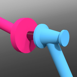
The 'Pin' constraint type is a rigid constraint meant to rigidly attach two or more dynamic items together; almost literally like pinning the two items together. This can be useful to attach together two object with dramatically different Mass values, such as a the metal head of a hammer attached to its wooden handle. The heavier head will affect the overall of the hammer. It is also useful to rigidly combined shattered objects that are meant to break apart when combined with the 'Stress Break' function.
To apply a constraint automatically, users can select two items prior to invoking any of the Constraint types. The first item selected represents the master or parent item and will be populated as 'Body A' within the constraint, the second item selected will be the item that is constrained, also considered the auxiliary or child item and will be populated as 'Body B'. With the items selected, LMB+click on the 'Pin' constraint button, adding the constraint item to the 'Items List'. The default center location (position) of the Pin Constraint will be exactly half-way between the Body A and Body B objects with a line drawing to the centers of the constrained items.
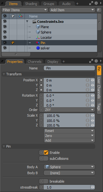 Name: This data field displays the current Constraint item name. Users may easily change it by LMB-clicking within the field and typing the new name.
Transform--
Position X/Y/Z: The Position XYZ values represents the initial center for constraint item in 3D world space, it also represents the center of mass relative to the item it is constraining. Based on its initial position, once a dynamics simulation is invoked, the constraining item will rotate and move based on its initial (resting) position.
Rotation X/Y/Z: The Rotation XYZ value represents the initial (resting) rotation of the constraining item.
Scale X/Y/Z: The Scale XYZ values have no direct affect over Constraints.
Pin--
Enable: The 'Enable' option toggles the Constraint item on or off. When enabled the constraint item will be considered during a dynamics simulation, when disabled, the constraint item will be ignored. However, disabled constraints are persistent across MODO sessions being saved with the scene, and retain their present settings.
SubCollisions: The 'SubCollisions' option, when enabled, allows constrained objects (especially those within a chain, not a literal chain but subsequent groupings) to collide with one another. When disabled (the default state), fewer calculation are required, however, constrained items may inter-penetrate each other. If this occurs users will want to enable SubCollisions.
Body A: The 'Body A' setting represents the item that is constrained to, this could also be considered the parent or master item.
Body B: The 'Body B' setting represent the item that is constrained, this could be considered the child or auxiliary item.
Breakable: The 'Breakable' option allows constraints to literally be broken apart when a certain stress threshold is reached, defined by the 'Break Stress' value. When the threshold is reached, the constraint will no longer have any affect on the constrained item, leaving it to be affected by any other forces present in the simulation.
Stress Break: The 'Break Stress' value determines the threshold when the constraint will no longer affect the constrained item. The 'Breakable' option must be enabled for this value to have any affect on the constraint.
Point Constraint
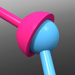
The Point Constraint attaches an object to a single point, providing an unrestricted dangling or swaying type motion when applied. To visualize this constraint, users can imagine the constrained item were tied to a piece of string which had been affixed to a specific point in 3D space, as the parent item moves, the constrained item will swing relative to the motions of the parent item.
To apply a constraint automatically, users can select two items prior to invoking any of the Constraint types. The first item selected represents the master or parent item and will be populated as 'Body A' within the constraint, the second item selected will be the item that is constrained, also considered the auxiliary or child item and will be populated as 'Body B'. With the items selected, LMB+click on the 'Point' constraint button, adding the constraint item to the 'Items List'. The default center location (position) of the Point Constraint will be exactly half-way between the Body A and Body B objects with a line drawing to the centers of the constrained items. Depending on your intentions, this might not be the optimal position for the Constraint. The motion of the child item (Body B) will originate from the position of the Constraint item itself, so it may need to be positioned appropriately.
 Name: This data field displays the current Constraint item name. Users may easily change it by LMB-clicking within the field and typing the new name.
Transform--
Position X/Y/Z: The Position XYZ values represents the initial center for constraint item in 3D world space, it also represents the center of mass relative to the item it is constraining. Based on its initial position, once a dynamics simulation is invoked, the constraining item will rotate and move based on this initial (resting) position.
Rotation X/Y/Z: The Rotation XYZ value represents the initial (resting) rotation of the constraining item.
Scale X/Y/Z: The Scale XYZ values have no direct affect over Constraints.
Point--
Enable: The 'Enable' option toggles the Constraint item on or off. When enabled the constraint item will be considered during a dynamics simulation, when disabled, the constraint item will be ignored. However, disabled constraints are persistent across MODO sessions being saved with the scene, and retain their present settings.
SubCollisions: The 'SubCollisions' option, when enabled, allows constrained objects (especially those within a chain, not a literal chain but subsequent groupings) to collide with one another. When disabled (the default state), fewer calculation are required, however, constrained items may inter-penetrate each other. If this occurs users will want to enable SubCollisions.
Body A: The 'Body A' setting represents the item that is constrained to, this could also be considered the parent or master item.
Body B: The 'Body B' setting represent the item that is constrained, this could be considered the child or auxiliary item.
Breakable--
Breakable: The 'Breakable' option allows constraints to literally be broken apart when a certain stress threshold is reached, defined by the 'Break Stress' value. When the threshold is reached, the constraint will no longer have any affect on the constrained item, leaving it to be affected by any other forces present in the simulation.
Stress Break: The 'Break Stress' value determines the threshold when the constraint will no longer affect the constrained item. The 'Breakable' option must be enabled for this value to have any affect on the constraint.
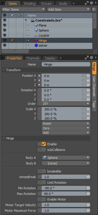
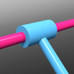
Hinge Constraint
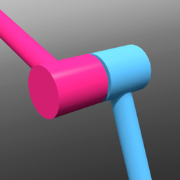
The Hinge Constraint limits the rotation movement of an object to swivel as if fixed by a hinge joint like that of a door. However, as a door hinge is limited by the collision of the opposing hinge plate, the hinge constraint offers unlimited rotation, much like a wheel axle. Users can add a rotation range limit to the joint to produce the more limited motion of the door hinge. The Hinge constraint is represented in the viewport as a circle around the point of rotation. Additionally users can apply a Motor force to the joint making it possible to create wheels that spin and move items forward.
To apply a constraint automatically, users can select two items prior to invoking any of the Constraint types. The first item selected represents the master or parent item and will be populated as 'Body A' within the constraint, the second item selected will be the item that is constrained, also considered the auxiliary or child item and will be populated as 'Body B'. With the items selected, LMB+click on the 'Hinge' constraint button, adding the constraint item to the 'Items List'. The default center location (position) of the Hinge Constraint will be exactly half-way between the Body A and Body B objects with a line drawing to the centers of the constrained items. Depending on your intentions, this might not be the optimal position for the Constraint. The motion of the child item (Body B) will originate from the position of the Constraint item itself, so it may need to be positioned appropriately.
 Name: This data field displays the current Constraint item name. Users may easily change it by LMB-clicking within the field and typing the new name.
Transform--
Position X/Y/Z: The Position XYZ values represents the initial center for constraint item in 3D world space, it also represents the center of mass relative to the item it is constraining. Based on its initial position, once a dynamics simulation is invoked, the constraining item will rotate and move based on this initial (resting) position.
Rotation X/Y/Z: The Rotation XYZ value represents the initial (resting) rotation of the constraining item.
Scale X/Y/Z: The Scale XYZ values have no direct affect over Constraints.
Constraint--
Enable: The 'Enable' option toggles the Constraint item on or off. When enabled the constraint item will be considered during a dynamics simulation, when disabled, the constraint item will be ignored. However, disabled constraints are persistent across MODO sessions being saved with the scene, and retain their present settings.
SubCollisions: The 'SubCollisions' option, when enabled, allows constrained objects (especially those within a chain, not a literal chain but subsequent groupings) to collide with one another. When disabled (the default state), fewer calculation are required, however, constrained items may inter-penetrate each other. If this occurs users will want to enable SubCollisions.
Body A: The 'Body A' setting represents the item that is constrained to, this could also be considered the parent or master item.
Body B: The 'Body B' setting represent the item that is constrained, this could be considered the child or auxiliary item.
Breakable: The 'Breakable' option allows constraints to literally be broken apart when a certain stress threshold is reached, defined by the 'Break Stress' value. When the threshold is reached, the constraint will no longer have any affect on the constrained item, leaving it to be affected by any other forces present in the simulation.
Stress Break: The 'Break Stress' value determines the threshold when the constraint will no longer affect the constrained item. The 'Breakable' option must be enabled for this value to have any affect on the constraint.
Limit Rotation: The hinge is not initially limited in its rotation. By enabling the 'Limit Rotation' option, users can constrain the range of rotation that can be applied to the constraint, similar to the motion of a door hinge that is allowed to only swing so far.
Min/Max Rotation Limit: The first Minimum value sets the lower extreme of the of the rotation clamping, while the second Maximum value limits the upper extreme value.
Enable Motor: Normally a hinge is only affected by the available forces in a dynamic simulation. Using the 'Enable Motor' toggle will allow users to apply a rotational Force to the Body B item making it spin around the Hinges constraints location. Speed of spinning is controlled by the Mass of the connected objects, combined with the 'Motor Target Velocity' and the 'Motor Maximum Force'.
Motor Target Velocity: When this value is non-zero it applies a rotational motion to the 'Body B' item like a wheel, positive value rotate the item forward and negative values rotate it in reverse. The direction of the motion is based on the initial position of the constraint. The motor will attempt to achieve the defined Target Velocity taking into account forces, mass as well as any collisions it encounters.
Motor Maximum Force: Determines the strength of how the Motor reaches its target velocity and how it reacts to collision items.
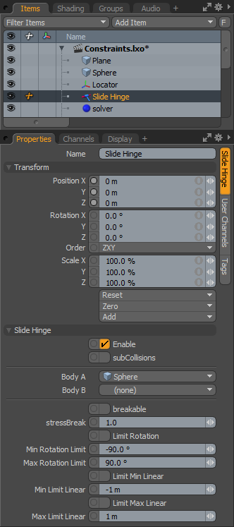
Slide Hinge Constraint
The Slide Hinge Constraint combines the dynamic actions of the 'Hinge' with a 'Slide' constraint, providing the rotation movement of the hinge with the addition of the linear back-and-forth sliding motion of the 'Slide'.
To apply a constraint automatically, users can select two items prior to invoking any of the Constraint types. The first item selected represents the master or parent item and will be populated as 'Body A' within the constraint, the second item selected will be the item that is constrained, also considered the auxiliary or child item and will be populated as 'Body B'. With the items selected, LMB+click on the 'Slide Hinge' constraint button, adding the constraint item to the 'Items List'. The default center location (position) of the Slide Hinge Constraint will be exactly half-way between the Body A and Body B objects with a line drawing to the centers of the constrained items. Depending on your intentions, this might not be the optimal position for the Constraint. The motion of the child item (Body B) will originate from the position of the Constraint item itself, so it may need to be positioned appropriately.
 Name: This data field displays the current Constraint item name. Users may easily change it by LMB-clicking within the field and typing the new name.
Transform--
Position X/Y/Z: The Position XYZ values represents the initial center for constraint item in 3D world space, it also represents the center of mass relative to the item it is constraining. Based on its initial position, once a dynamics simulation is invoked, the constraining item will rotate and move based on this initial (resting) position.
Rotation X/Y/Z: The Rotation XYZ value represents the initial (resting) rotation of the constraining item.
Scale X/Y/Z: The Scale XYZ values have no direct affect over Constraints.
Slide Hinge--
Enable: The 'Enable' option toggles the Constraint item on or off. When enabled the constraint item will be considered during a dynamics simulation, when disabled, the constraint item will be ignored. However, disabled constraints are persistent across MODO sessions being saved with the scene, and retain their present settings.
SubCollisions: The 'SubCollisions' option, when enabled, allows constrained objects (especially those within a chain, not a literal chain but subsequent groupings) to collide with one another. When disabled (the default state), fewer calculation are required, however, constrained items may inter-penetrate each other. If this occurs users will want to enable SubCollisions.
Body A: The 'Body A' setting represents the item that is constrained to, this could also be considered the parent or master item.
Body B: The 'Body B' setting represent the item that is constrained, this could be considered the child or auxiliary item.
Breakable: The 'Breakable' option allows constraints to literally be broken apart when a certain stress threshold is reached, defined by the 'Break Stress' value. When the threshold is reached, the constraint will no longer have any affect on the constrained item, leaving it to be affected by any other forces present in the simulation.
Stress Break: The 'Break Stress' value determines the threshold when the constraint will no longer affect the constrained item. The 'Breakable' option must be enabled for this value to have any affect on the constraint.
Limit Rotation: The hinge part of this Constraint is not initially limited in its rotation. By enabling the 'Limit Rotation' option, users can constrain the range of rotation that can be applied to the constraint, similar to the motion of a door hinge that is allowed to only swing so far.
Min/Max Rotation Limit: The first Minimum value sets the lower extreme of the of the rotation clamping, while the second Maximum value limits the upper extreme value.
Limit Min/Max Linear: By default, the motion of the constrained item will not be limited across the length of the constraining line. Enabling the 'Upper' and/or 'Lower' limits allows users to restrict the motion to a specific range determined by the Min/Max position values.
Min/Max Limit Linear: When the 'Limit Lower/Upper X' values are enabled, users can define a range as a distance value offset from the constraints center position.
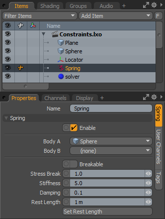
Spring
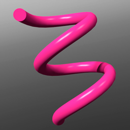
The 'Spring' is a special constraint the mimics the motion of an actual coiled spring. The Spring constraint produces a motion similar to the 'Point Constraint' swinging and swaying, with the addition of the stretching and compression action of a spring. It is represented in the viewport by a coil that will extend and compress as objects move during a simulation.
To apply a Spring constraint automatically, users can select two items prior to invoking the Spring constraint option. The first item selected represents the master or parent item, typically this is the fixed or keyframe animated item. The second item selected will be the item that is constrained, also considered the auxiliary or child item and will be constrained to the motion of the Spring. With the items selected, LMB+click on the 'Spring' button in the Dynamics toolbox, adding the Spring item to the 'Items List'. By default, the spring will stretch between the center points of the two selected objects. While Constraints can be added manually to a scene by way of the item list, automatically assigning them to items is the preferred method as it will also automatically define the constraints position relative to the selected items.
 Name: This data field displays the current Spring items name. Users may easily change it by LMB-clicking within the field and typing the new name.
Spring--
Enable: The 'Enable' option toggles the Spring item on or off. When enabled the Spring will be considered during a dynamics simulation, when disabled, the Spring item will be ignored. However, disabled items are persistent across MODO sessions being saved with the scene, and retain their present settings.
Body A: The 'Body A' setting represents the item that is constrained to, this could also be considered the parent or master item.
Body B: The 'Body B' setting represent the item that is constrained, this could be considered the child or auxiliary item.
Breakable: The 'Breakable' option allows the Spring to literally be broken apart when a certain stress threshold is reached, defined by the 'Break Stress' value. When the threshold is reached, the Spring will no longer have any affect on the constrained item, leaving it to be affected by any other forces present in the simulation.
Stress Break: The 'Break Stress' value determines the threshold when the Spring will no longer affect the constrained item. The 'Breakable' option must be enabled for this value to have any affect on the Spring.
Stiffness: The amount of force it takes to compress the spring (shorten its length). A stiffer spring is harder to compress.
Damping: During a simulation, a spring will oscillate between extended and compressed. The 'Damping' effect reduces the amplitude of the springs oscillations over time.
Rest Length: The 'Rest Length' represents the length of the spring when it is not in motion. This can also be considered the distance between the two constraining items when the spring reaches equilibrium.
Top