Accessible from the menu bar under "System > Preferences...", the MODO preferences define the default behavior for a variety of options and functions in MODO, further customizing the application to suit the particular tastes, needs and workflow of the individual user. The Preferences are organized into multiple categories that each deal with specific areas of customization for the application. Users can select any of the categories below to display the documentation that relates to that particular corresponding section.
Item Tag Definitions--
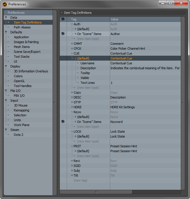
The 'Item Tag Definitions' editor is used to provide user names, descriptions and tooltips for items, which show up in the 'Tags' subtab in the Item Properties viewport. Â The 'Tags' themselves are four-character identifiers associating arbitrary strings. Â Each item can have any number of tags, although only one of each type of tag. Â The editor also allows the number of lines to be set (for a multi line tags like "Comment") and allows tags to be hidden from the user (for internal tags used by scripts/plug-ins). Â The 'Item Tag' Editor (which is actually a viewport embedded into the prefs form) is intended for use mostly by scripting and plug-in developers. They can be helpful to users in that they allow arbitrary information to be associated to specific items layers, such as adding instructions within a scene that applies to a certain item.
Path Aliases--
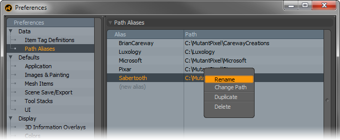
Path Aliases provide users a means to easily move MODO scenes between disparate computer hardware. Users can define an Alias that represents an absolute path on the local system. Any files within a scene that contain the defined path will use the Alias instead. When the scene file is moved to the next system, if the same Aliases are defined with appropriate paths, when MODO comes across any Alias in the scene the provided path is used. For example--
Machine 1 path = "C:\Animations\LostSkeleton\Scenes\" This path is defined as an alias called 'LostSkeleton'. When any files are loaded into the scene from this directory, their path will simply be called 'LostSkeleton' internally.
Machine 2 path = "/Users/Lighting/Scenes/LostSkeleton" this path is also defined with the alias 'LostSkeleton'. Users can copy the files from Machine 1 into this directory. When MODO opens the scene, when it comes across images saved in the folder 'LostSkeleton' the path alias defined on machine 2 is used to search for the images for loading. Only the Alias itself needs to be identical, the paths do not. Of course the content will need to exist within each locale as well.
There are also options available by RMB+clicking on the Alias and Path to 'Rename' an alias, to 'Change Path'. Users can also 'Duplicate' and 'Delete' aliases.
Application--
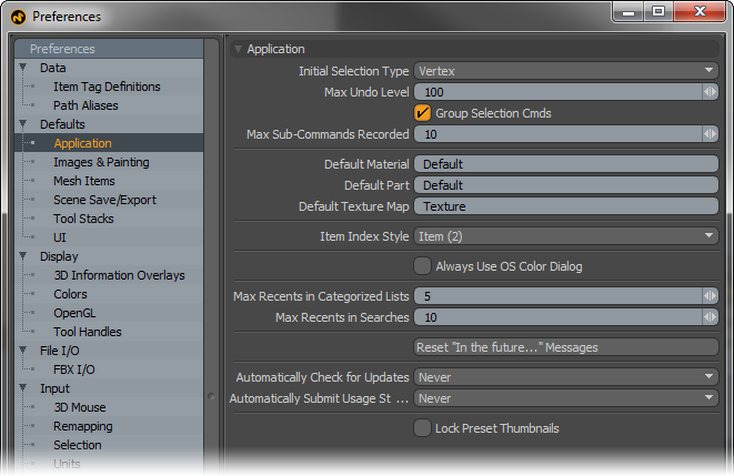
Initial Selection Type: This option simply determines the default selection mode when MODO is first opened.
Max Undo Levels: The 'Max Undo Levels' controls the maximum number of steps backwards users can go in the history. The default value of '100' is generally very good at allowing users leeway to step backwards through the history. Increasing the value will allow users to go further back in time, so to speak, but will also increase memory usage. For memory intensive scenes, it may be beneficial to reduce this value to reduce total memory overhead.
Group Selection Cmds: When this option is enabled, MODO will group multiple consecutive selection actions into a single undoable action. The grouping size is determined by the 'Max Sub-Commands Recorded' Value.
Max Sub-Commands Recorded: This option determines the maximum number of consecutive actions grouped into a single 'undoable' action when the 'Group Selection Cmds' option is enabled.
Default Material: This option determines the default material tag applied to newly created polygons. This will also be the default name that appears in the 'Polygon Set Material' dialog box when defining new material tags.
Default Part: This option determines the default name used for new part tags. Name appears in the 'Polygon Set Part' dialog box.
Default Texture Map: This option determines the default name used for new and auto-generated UV maps. Name appears in the 'VMap List' viewport.
Item Index Style: Scenes cannot have multiple items with identical names (much like program files in the same folder), when this occurs, MODO will automatically rename the item, be it a shader tree layer, item layer or vertex map, appending a numeral to the end of the defined names in a style determined by this option.
Use OS Color picker: When enabled, MODO will default to using the operating system specific color picker, duplicating the behavior of pre-501 versions. When disabled, MODO will use its own internal color picker.
Max Recents in Categorized Lists: Many 'Add' menus, such as 'Add Layer' in the Shader Tree or 'Add Item' in the Item list have a 'Recent' menu at the top of the list to hold the most recent items added during the present MODO session. Users can adjust this setting to determining the maximum number of recent entries in the menu.
Max Recents in Searches: Several of the list viewports (like the Items List and the Shader Tree) offer a search function through the use of the small 'F' button. Previous search terms can be cached in the dropdown menu when searching, allowing speedier subsequent searches for the same term. The 'Max Recents in Searches' determines the number of search terms that will be cached for this purpose.
Reset "In the Future...": Messages: Many pop-up dialog boxes in MODO provide a function to dismiss them in the future. For example, when welding pairs of points consecutively, users can dismiss future popups of the same dialog box using the 'In the Future' setting in the pop-up itself. Users can use this button to reset all these types of pop-ups to their factory installed state (meaning, if they have been dismissed permanently, this will bring them back).
Automatically Check for Updates: This option would normally be used to determine how often MODO checks the update server to see if a newer version is available. However, MODO Steam Edition is updated automatically through Steam, and is therefore unnecessary.
Automatically Submit Usage Statistics: Usage statistics of MODO sessions can be submitted to The Foundry that helps us to determine application stability and in the case of instability, help us in determining the source of the problem. If users wish to help out in the efforts to improve MODO, they can opt to submit this information to us 'Every Launch', 'Daily' or 'Weekly'. Selecting the 'Never' option disables the function completely. The information collected and submitted is the MODO build version, the current OS, the last 10 commands run prior to any crash/hang, the duration of the last session and if it ended successfully or terminated in a crash/hang event. No personal information is collected. We hope you'll help us in our efforts to improve MODO, but we also understand should you choose to opt-out.
Lock Preset Thumbnails: When this option is enabled, saving over any existing presets will retain the existing thumbnail.
Images & Painting--
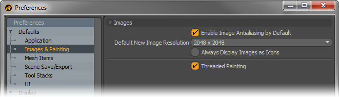
Enable Image Antialiasing by Default: MODO provides an image antialiasing function to smooth the rendered result of bitmap images. In certain instances, especially with lower resolution images, images may appear soft of fuzzy when rendered. By default, MODO always enables this option found in the Image Map properties. Users can modify this behavior with this option having antialiasing always disabled by default. Of course users may also override the default value on a per image basis in the image map properties itself.
Default New Image Resolution: When creating a new blank image for painting or baking, this value defines the default resolution. Users can also change this at the time the image is created.
Always Display Images as Icons: Forces MODO to show images in the Clips list as Icons.
Threaded Painting: This option, enabled by default, threads the painting and sculpting tool into multiple processes, providing better performance. It is possible, however, in some dual or single core systems this setting should be disabled.
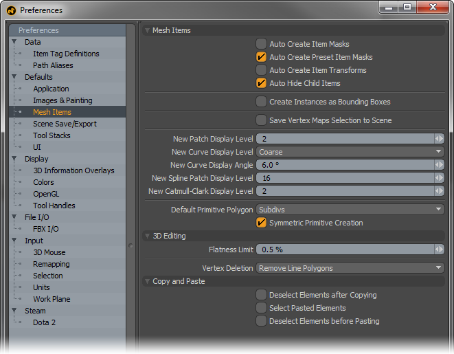
Mesh Items--
Auto Create Item Masks: When this option is enabled, an 'Item Mask' is automatically generated for each new item layer that is created in the Items list.
Auto Create Preset Item Masks: When this option is enabled, an 'Item Mask' is automatically generated for each new mesh preset item that is added to any scene. This can be especially helpful to limit shader tree layers to the specific preset should there be material tag naming collisions (i.e. identical named material tags between existing layers and the preset).
Auto Create Item Transforms: When new items are created in the item list, by default, they do not have specific transform channels in the channels viewport ('Position', 'Scale' and 'Rotate'). Enabling this option instructs MODO to create the 3 basic transform channels for all new items.
Auto Hide Child Items: Users can create hierarchies of elements in a scene, and relate elements under 'Group Locators' for organization. The 'Auto Hide Child' option, when enabled will allow users to toggle visibility of all related child layers when any parent layer is toggled. When disabled, layer visibility in a hierarchy is toggled individually per layer.
Create Instances as Bounding Boxes: By default, MODO displays instanced items as full wireframe representations of the source item. When this option is enabled, MODO will instead display only bounding box representations of instanced items. This can improve display performance for heavily instanced scenes.
Save Vertex Maps Selection to Scene: When this option is enabled, any selected vertex maps will remain selected when the file is closed and later re-opened. When disabled, all vertex map selections will reset with no maps being selected when the file is re-opened.
New Patch Display Level: Determines the default Patch level for Subdivision Surfaces items. Higher values produce smoother results but generate more geometry. Users can manually adjust the Patch display level for each Item in the Items Properties.
New Curve Display Level: Determines the default amount for how smoothly Curves are displayed in the 3D viewports. Users can choose between 'Course', 'Medium' and 'Fine'.
New Curve Display Angle: The 'New Curve Display Angle' defines the default value that controls how curves are quantized for display and freezing. This is analogous to the patch resolution for subdivision surfaces.
New Spline Patch Display Level: This option determines the default 'Spline Patch Level' for Patched surfaces. Users can manually adjust this value in the Item properties.
New Catmull-Clark Display Level: Determines the default Catmull-Clark Subdivision Surfaces subdivision level. Higher values produce smoother results but generate more geometry. Users can manually adjust the subdivision level for Catmull-Clark surfaces in the Items Properties viewport.
Default Primitive Polygon: Certain Primitive mesh objects (such as the 'Sphere' and 'Torus') have an option that sets the type of polygons the tool generates. The 'Default Primitive Polygons' option defines the default state for these values.
Symmetric Primitive Creation: When this option is enabled in conjunction with the symmetry option, any primitives that are created, such as a cube or a sphere, an identical mirrored version is also created across the line of symmetry.
3D Editing--
Flatness Limit: This value determines the threshold at which a polygon is considered to be planar or non-planar. Higher values will designate less and less polygons as being non-planar. Users can use the Statistics panel to select these types of polygons automatically.
Vertex Deletion: This setting determines what action MODO takes when all but two vertices of any given polygon are deleted-
Remove Line Polygons- This option will remove the remaining 2-point polygons that result from the action, but retains the vertices from surrounding polygons if shared. This option is the default value and is recommended for most users.
Keep All Polygons- This options retains the 2-point polygons (also known as line polygons). The remaining 2-point polygon does not render, but can be used like a polygon or an edge, and can be extruded and extended into a full polygon.
Copy and Paste--
Deselect Elements after Copying/Select Pasted Elements/Deselect Elements before Pasting: The default clipboard behavior in MODO is when Pasting 'Copied' elements, the original selection remained active and the newly pasted geometry is inserted unselected dictating a specific workflow or workarounds in certain situations, such as copying part of some geometry on top of itself into the same layer, there was no way to accurately select the newly inserted geometry without creating a new layer and shuffling the elements between them. With these options, users can now have MODO automatically select/deselect elements, also providing a workflow familiar to many graphics applications.
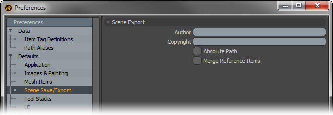
Scene Export--
Author/Copyright: These values, when defined, are embedded within saved and exported files (where supported).
Absolute Path: When this option is enabled, MODO will write all link references (such as those to images, MDDs and IES files) as Absolute Paths referencing their location to specific areas of a disc drive when saving files. When disabled, MODO uses relative paths to locate linked files.
Merge Reference Items: When utilizing Scene Reference items, users can enable this option to embed the referenced items into the scene file when saving, instead of having them remain external entities.
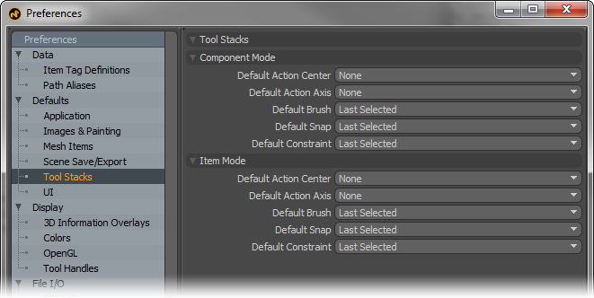
Tool Stacks--
The 'Tool Stacks' options allow users to define default states for different function for both the component selection modes (Vertices, Edges and Polygons) and for Items selection mode.
Default Action Center: Users can use this option to determine the default Action Center when MODO is first opened.
Default Action Axis: Users can use this option to determine the default Action Axis when MODO is first opened.
Default Brush: Users can use this option to determine the default Brush Tip that will auto select when utilizing any sculpting or painting brush. 'Last Selected' will obviously return the Brush to its prior state.
Default Snap: Users can use this option to determine the default Snap state. This is especially useful when utilizing the 'X' snap toggle keyboard shortcut. Users can define their default state and whenever pressing 'X' during a modeling operation, this will be the state MODO enters into for snapping.
Default Constraint: Users can use this option to determine the default Constraint type when MODO is first opened.
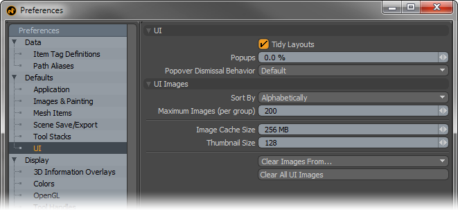
UI--
Tidy Layouts: MODO's interface is made up from a collection of viewports. Viewports always have a frame users can use to resize the window. When multiple viewports are nested within each other, multiple viewport frame borders become unnecessary, the 'Tidy Layouts' option, enabled by default, removes these subsequent viewport frames providing a few pixels of additional screen real-estate as well as a cleaner UI. However, user may wish to disable the setting to better see how viewports relate to one another for the purposes of interface customization (not applicable to MODO Steam Edition).
Popups: The 'Popups' percent value controls the transparency of Popup windows, Popovers and Pie Menus. Higher values make the Popups more transparent, allowing the background to been seen through them (making them less obtrusive) but also more difficult to read the contents. This may affect performance on some systems.
Popover Dismissal Behavior: This options can be used to override the dismissing behavior for Popovers. The 'Default' option retains the hard coded behavior. 'Force Click-Off' makes sure that Popovers remain open until explicitly clicked away from and 'Force Roll-Off' will dismiss the window when the cursor is simply rolled away from it. This only affect simple popovers, point at popovers are always click-off.
UI Images--
Sort By: This option determines how images are sorted in UI viewports such as the Clip Browser function. Images are sorted 'Alphabetically' or they are sorted by 'Age' with the most recently imported images appearing at the top of the list.
Maximum Images (per group): Determines the maximum number of clips (stills or animations) that can be loaded into a Clip Browser.
Image Cache Size: Determines the maximum amount of RAM dedicated to holding all user interface thumbnails, such as those generated for imported images, image inks and brush tip images.
Thumbnail Size: Determines the pixel resolution for auto-generated user interface thumbnails.
Clear Images From...: Users can open this menu to choose from multiple user determined options to remove images from in the user interface. Once a particular command is invoked, images in that functions 'Clips Browser' will be removed from display, clearing memory.
Clear All UI Images: This option will clear all latent images from the various Clip Browsers for the tools, i.e. the Image Ink browser, Brush Tip Browser, etc.
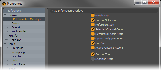
3D Information Overlays (aka 3D viewport HUD)
Each 3D viewport displays a variety of information as a HUD (heads-up display) directly in the viewport. Users can control what information is viewed by these toggles-
Morph Map- Displays the name of the currently selected morph map, if available.
Current Selection- Displays selected element information, based on the current mode (component, item or otherwise).
Reference Item-
Selected Channel Count- Displays the number of currently selected (active ) channels in the 'Channels' viewport useful for keyframing.
Deformers Enable State- Displays current state of 'Deformers'.
OpenGL Polygon Count- Displays the number of GL polygons, including those added by Subdivision Surfaces.
Grid Size- Displays the real-world measurement equivalent of the current grid divisions.
Active Passes and Actions- Displays any active 'Passes' and/or 'Actions' by name that are selected
Current Tool- Displays current tool information as well as info for 'Falloffs', 'Action Centers' and 'Snap'.
Snapping State- Displays the current enabled options for Snapping.
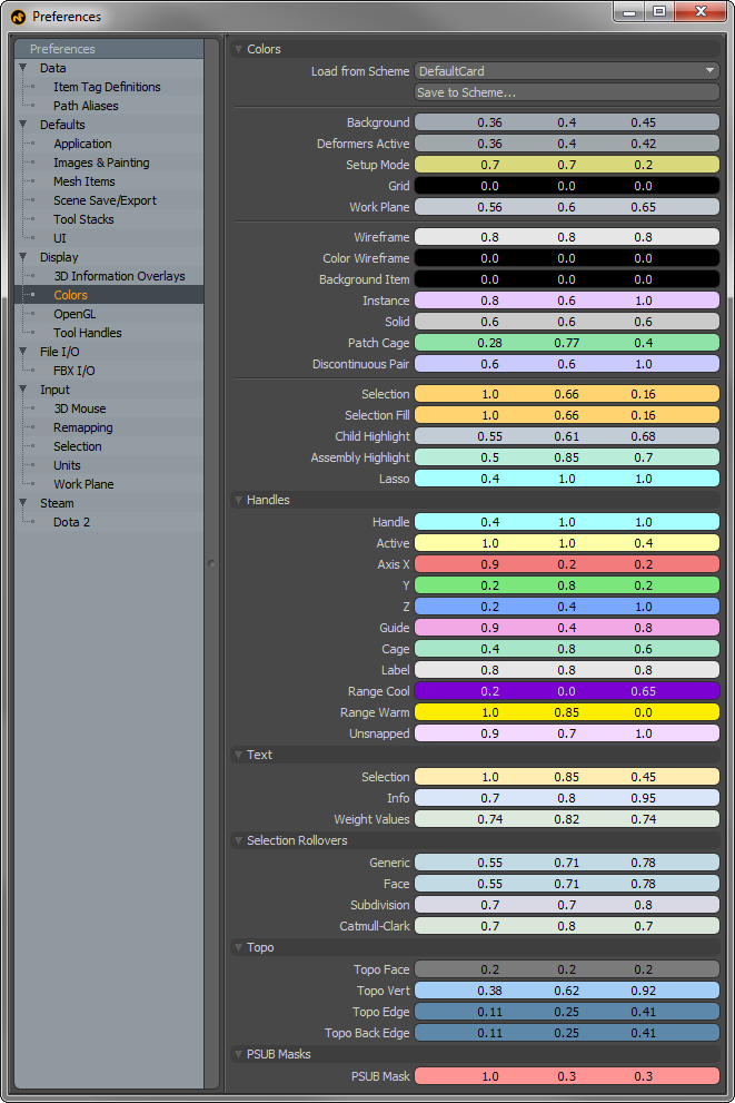
Colors--
Users can customize the colors of many aspects of MODO related to the 3D viewports (application specific viewports don't have directly editable color schemes). Users should note that modifying colors in 'Preferences' will not modify the actual default viewport colors. In order to apply a color scheme to a viewport, users will first need to adjust the colors in this section, then use the 'Save to Scheme' function and assign a new name using this dialog box-
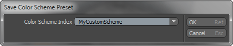
Once a scheme name has been set, users will need to switch back to the particular 3D viewport they wish to apply the scheme to. Presets can be applied on a per-viewport basis, determined by its 'Active' status. Active viewports are separated by the thumb changing to an orange color (the thumb is the small dimple in the upper left corner of a 3D viewport). Users can set any viewport as 'Active, by simply LMB+clicking anywhere over the viewport window. Next, invoke the menu bar command "View > Viewport Color Scheme" and select the previously saved scheme from the drop-down menu list. The following elements of MODO can be customized--
Background- The viewport background color when GL Background option is set to 'None' or 'Gradient'.
Grid- The main ground plane grid visible in every 3D perspective viewport.
Work Plane- The adjustable construction plane.
Wireframe- Default 'Uniform' wireframe draw color, can be over ridden by individual item Draw options.
Color Wireframe- Default 'Color' wireframe draw color, can be overridden by individual item Draw options.
Background Item- Inactive mesh color, also considered Background or Unselected.
Instance- Instanced item duplicates.
Solid- Geometry display color when using the 'Solid' GL viewport display style.
Patch Cage- When SubDivision display cage option is enabled, this determines its color.
Discontinuous Pair- Color referencing discontinuous edges in UV mode.
Selection- Element selection color for all selection types, Component, Item and otherwise.
Selection Fill- Fill Color of Selected Elements, can be set different from selection itself.
Child Highlight- When a Parent item is selected, child items can have a custom color referencing their relationship to the selected item.
Assembly Highlight- Highlighted mouse-over color of Assemblies.
Lasso- Color of line drawn when drag selecting elements with a lasso.
Handles--
Handle- Unselected action area of tool.
Active- Selected Action area of tool.
Axis X/Y/Z- Colors for constrainable tool handles for each axis.
Guide- When using Snapping > Constrain to > Guides, this option determines guide color.
Cage- Color for Spline/Curve Cage edges.
Label- Item Label as determined by 'Display' options.
Range Cool- When "View > Show Falloffs" is enabled, determines cool range of falloff.
Range Warm- When "View > Show Falloffs" is enabled, determines warm range of falloff.
Unsnapped- When snapping elements, a small pre-highlight displays when elements are in close proximity, defined by this color.
Text--
Selection- Color for on-screen informational text display of selected elements.
Info- Color for on-screen informational text display.
Weight Values-
Selection Rollovers--
Generic- Generic selection roll-over pre-highlighting color.
Face- Geometry face roll-over pre-highlighting color.
Subdivision- MODO Subdivision surface geometry roll-over pre-highlighting color.
Catmull-Clark- Catmull-Clark geometry roll-over pre-highlighting color.
Topo
Topo Faces- Polygon faces while using the 'topo' display mode option.
Topo Vert- Vertices while using the 'topo' display mode option
Topo Edge- Edges while using the 'topo' display mode option
Topo Back Edge- Rear facing polygon edges while using the 'topo' display mode option
PSUB Masks
PSUB Mask- Color of sculpting mask overlay
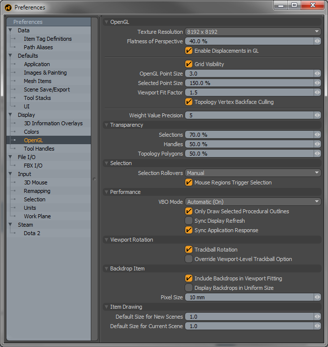
OpenGL--
Texture Resolution: This values (set as powers of '2') determines the largest bitmap texture size displayable in MODO 3D viewports before MODO will resort to mip-mapping, which is a method of subsequent resamples of an image at a lower resolution that enable faster image drawing to the 3D viewport. Higher settings will increase image quality, but require greater video ram.
Flatness of Perspective: This option determines the amount of perspective in the 3D perspective viewport. Similar to the 'Field of View' option in the Camera options panel. The higher the value, the flatter the perspective, the lower the value the more distorted and extreme the perspective becomes.
Enable Displacement in GL: This option determines if displacement effects are displayed in the GL viewports as actual polygon displacement. When disabled, displacement will simply display in the 3D viewports as a bump map.
Grid Visibility: This option determines the default visibility state of the ground plane grid visible in 3D viewports. It is enabled (visible) by default.
OpenGL Point Size: This option determines the size of the on-screen display of vertices, specified in screen pixels. The default value is 3. Consequently, it also controls the selection hit area for selecting vertices.
Selected Point Size: To make it easier to see their on-screen display, selected (highlighted) vertices can be displayed larger in the 3D viewport, an amount determined by this option. Scale is based off the original 'OpenGL Point Size" option.
Viewport Fit Factor: Users can automatically frame the view of all the elements of a scene to the bounds of the active viewport by using the menu bar commands "View > Fit All" or "View > Fit Selected" (or keyboard equivalents 'A' or 'Shift+A' respectively). This option determines the scaling of the fit. '1' is essentially 100%, fitting the bounding box of the elements to that of the viewports shortest length. The default of '1.5' gives a little breathing room around the elements and ensures the view fits into view regardless of bounding box size.
Topology Vertex Backface Culling: When enabled, this option disables the display of vertices for rear facing polygons while using the topology display mode. This can make it easier to distinguish foreground vertices when editing.
Weight Value Precision: If a Weight Map and Vertices are selected with the 'Show Weight Values' option enabled, then the 'Weight Value Precision' option determines the number of decimal places shown for the weight values in the GL viewport.
Transparency--
Selection: When viewing a selection through an opaque surface, this option determines the opacity of the selection highlighting through the surface (kind of like an X-ray). Especially helpful in differentiating front and rear facing selections.
Handles: When viewing tool handles through an opaque surface, this option determines the opacity of the handle itself, making it possible to see the handles through the surface (kind of like an X-ray).
Topology Polygons: This option determines the transparency of forward facing polygons while in the topology display mode.
Selection--
Selection Rollovers: Pre-highlighting of elements in a scene helps users to make better selection, making it clear as to what elements will be selected when the mouse button is clicked. The 'Selection Rollover' option determines how the highlighting occurs-
None- No pre-highlighting of elements in the scene.
Manual- Pre-highlighting of elements is based on the current mode (vertices, edges, polygons, items, etc.).
Closest- Pre-highlighting the nearest geometric component element regardless of mode.
Mouse Regions Trigger Selections: With this option enabled, users can automatically switch between component modes (vertex, edge, polygon) by simply RMB+clicking over the target element. Can be combined with 'Closest' selection rollover to aid in determining the proper element to click on.
Performance--
VBO Mode: VBO stands for 'Vertex Buffer Object', a method of working and displaying geometry in OpenGL. VBO's offer substantial performance gains over the older immediate mode rendering method, but may also cause problems with older video cards (or video cards with lacking drivers). MODO will try to determine the best mode when set to 'Auto', depending on the video cards driver. Users can also manually enable/disable the option with the On/Off options to increase stability.
Only Draw Selected Procedural Outlines: When this option is enabled, MODO will only draw the surface outline for procedural geometry. When disabled, MODO will draw any individual triangles that make up the surface.
Sync Display Refresh: Also know n as 'Vsync', when enabled this option will help with tearing in the GL viewports but may cause lag with larger meshes and lower framerates.
Sync Application Response: When enabled, this option will sync the application with the 3D OpenGL viewports reducing lag, but it can sometime also significantly reduce the 3D viewports framerate (entirely dependent on the Scenes contents).
Viewport Rotation--
Trackball Rotation: This options determines the default navigation rotational type. Trackball style navigation is a common way to rotate the view of a scene, as if the viewport itself was a giant trackball, allowing multiple axes rotation based on the mouse's viewport position. Disabling this option limits viewport rotations to only two axes. This setting can be over-ridden on a per viewport basis.
Override Viewport-Level Trackball Option: When enabled, this option disabled an individual viewports ability to over-ride the Viewport Rotation preference setting, in essence locking all viewport rotation options to the same preference setting.
Backdrop Item--
Include Backdrops in Viewport Fitting: When using the 'Fit' function of a viewport, enabling the 'Include Backdrops' option will account for the size of any visible Backdrop items when calculating bounding box size for the fit action.
Display Backdrops in Uniform Size: When this option is enabled, Backdrop items will ignore the image size, instead basing the scale of the backdrop off of the items 'Scale' value.
Pixel Size: When importing bitmap images for use as Backdrops, the 'Pixel Size' option determines the measurement of a single pixel in an image upon import, allowing users to place backdrop images scaled to real world size. For example, if 'Pixel Size' is set at 10mm, then a 512x512 image will import at 5.12 meters in size.
Item Drawing--
Default Size for New Scenes: Determines the default drawing size in the 3D viewports for non-mesh items, such as Cameras and Lights. Users can also adjust the scaling values manually in the 'Display' viewport.
Default Size for Current Scene: Determines the default drawing size in the 3D viewports for non-mesh items added after a scene is created; such as Cameras and Lights when added to a new scene. Users can also adjust the scaling values manually in the 'Display' viewport.
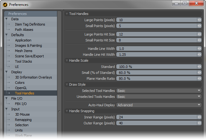
Tool Handles--
Large\Small Points: Determines the visible size, in pixels, of manipulator handles displayed on tools (such as those on the Curve drawing tools).
Large\Small Points Hit Size: Determines the hit range, or area where a mouse click will affect the particular tool handle. Typically this value will be larger than the handle size to make it easier to select a particular handle, but making it too large can make it difficult to select a specific handle in a tight cluster.
Handle Line Width: Determines the width, in pixels, of the lines drawn for tool handles, such as the widgets for Move, Rotate and Scale.
Handle Line Hit Width: Determines the hit range, or area where a mouse click will affect the particular tool handle. Typically this value will be larger than the handle size to make it easier to select a particular handle.
Handle Scale--
Standard: Users with very large or very small screens may prefer to set the default size of the tool handles larger or small using this setting. Handles will stay consistent in size regardless of viewport scaling. Users can also interactively scale tool handles by pressing the '-' and '=' keys. (easier to remember as '-' & '+' [minus and plus] though)
Small (% of Standard): Some tools have a smaller secondary handle. Users can adjust its size here based as a percentage of the "Standard' amount.
Plane Handle Ratio: Many tools have additional plane handles, that constrain actions to two axes simultaneously. Users can adjust the plane tool handles size based on the 'Standard' amount.
Draw Style--
Selected Tool Handles: Determines the default drawing behavior for tool handles-
Invisible- No handles display in the viewport.
Basic- Basic tool handles display allowing users to constrain certain function when used, based on the particular tool.
Advanced-
When present/available, additional controls or handles will appear on screen to aid in setting certain options for a tool or item. For example, when selecting the Camera item with and any tool with 'Advanced' handles, additional controls become visible for setting 'Focal Distance' and 'F-Stop'.
Unselected Tool Handles: Depending on the tool, additional handles may display in the viewport, especially those related to setting falloff positions and sizes. The 'Unselected Tool Handle' option determines the drawing options for these types of additional handles.
Auto-Haul Display: Some tools can be enhanced with additional on-screen controls. For example, advanced in-viewport sliders can specify Bevel 'Shift' and 'Inset'. This option determines whether or not to draw such additional helpers.
Off- Disables display of additional on-screen tool Auto-Haul Displays.
Basic- Displays only basic tool handles.
Advanced- Displays only advanced tool handles when available.
On- Displays on Screen Auto-Haul handles defaulting the settings of the preset itself as determined by its options in the Tool Pipe.
Handle Snapping--
These are the default values, in pixels, for the distance from a snapping target where the cursor first gets snapped.
Inner Range: Determines the actual snapping range.
Outer Range: Determines the range to highlighting elements for snapping to.
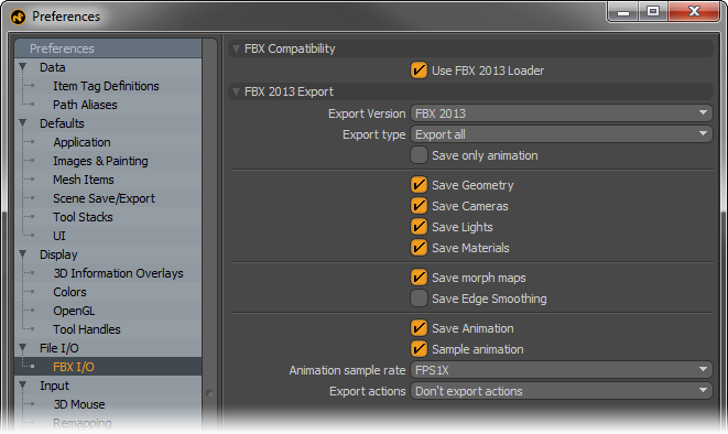
FBX Compatibility--
Use FBX 2013 Loader: When this option is enabled all FBX files opened will use the 2013 version of the FBX loader, when disabled modo will use the previous FBX 2010 version of the loader.
FBX 2013 Export--
Export Version: Users can choose which file format versions they wish to export to when saving FBX format files from modo.
Export Type: Defines how the elements will be exported with three self-explanatory options-- 'Export All' exports the entire scene, 'Export Selection' exports only the selected Item layers, and "Export Selection with Hierarchy" retains the parenting hierarchy of the selected layers.
Save Geometry: When this option is enabled, modo will export all polygonal geometry to the FBX format.
Save Cameras: When this option is enabled, modo will export all camera items to the FBX format.
Save Lights: When this option is enabled, modo will export all light items to the FBX format.
Save Morph Maps: When this option is enabled, modo will export Morph Maps as compatible Blend Shapes in the FBX format.
Save Edge Smoothing: When this option is enabled, an FBX specific command is used to compute geometric normals upon export. It is known to increase export times on large meshes, and therefore should remain disabled unless the users is certain it is necessary.
Save Animation: When this option is enabled, modo will export keyframed animations.
Sample Animation: When this option is enabled modo will bake out animated channels modifiers based on the animation sample rate.
Animation Sample Rate: This option determines the sampling rate for baked animations at either 1 frame (every frame) or 2 frame (every other frame).
Export Actions: This option controls how 'Actions; are exported, either not at all 'Don't Export Actions', or each Action is saved as a separate take 'Export Actions into Separate Takes'.
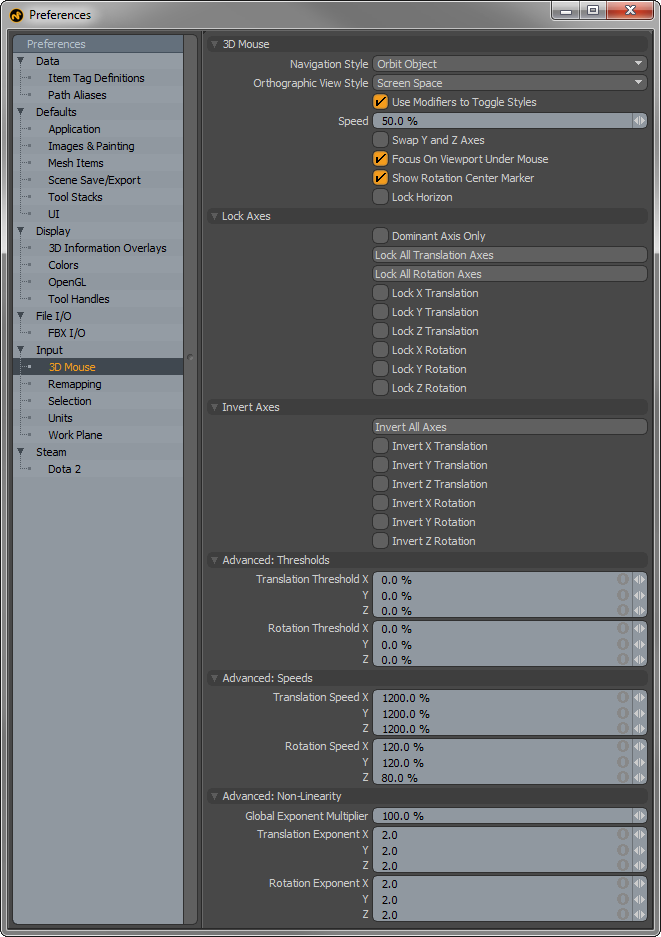
3D Mouse--
Navigation Style- The 3D Mouse provides two main navigation styles which users may select based on preference-
Camera Walkthrough- Â Moving the puck moves the viewport's camera as though you were moving the camera itself. Â Pushing the puck to the right moves the camera to the right (and thus the scene appears to move to the left). Â Can be thought of as similar to playing a first-person video game.
Object Orbit- Â Moving the puck moves the viewport's camera such that you seem to be moving the item in the view. Â Pushing the puck to the right moves the camera to the left (thus making it appear that the object is moving to the right). Â Twisting the puck rotates the camera around the object, as though the object was spinning around in front of you. Â The center of rotation is determined by the "blue dot" (aka "Auto Rotation Center"), which appears at the center of the viewport when you start manipulating the puck. Â If the item under dot fills >80% of the view, the blue dot represents a point on the surface of the model that is tracked in 3D space until you release the puck (at which point the blue dot will re-center at the center of the viewport when you touch the puck again). Â If <80% of the view is filled with the object, the object's bounding box center is used as the center of rotation.
Orthographic View Style:
World Space-Â The translation axes of the puck move in world space, irrespective of the current orthographic view. Â Thus, pushing left/right on the puck always moves on the world X axis, even if the orthographic view is showing the Left or Right (and in which case you won't appear to see any movement, since you're moving perpendicular to the view). Â Best used/demonstrated with the Model Quad view
Screen Space- The translation axes move relative to the current view: x20left/right moves on the horizontal axis, and up/down moves in the vertical axis. Pushing in/out will change the view's zoom
Screen Space (Swap Y and Z Axes)- Pushing the puck left/right will move left/right just like in Screen Space mode, but pushing the puck forward/backward (like a mouse on a desk) will move the screen up/down, while pulling up/down will zoom in and out. Basically, the Y and Z axes are swapped.
Use Modifiers to Toggle Styles: When enabled, 'Alt' toggles between the two 'Navigation Styles' as long as it is held down. Similarly, 'Shift' and 'Ctrl' will toggle between the two 'Orthographic View Styles' as long as they are held down.
Speed: This is a global speed modifier, a scaling value applied to the 3D mouse's input values to make the mouse move faster or slower. This is not capped to 100%, so you can set it to 200%, etc. if you want it to go faster.
Swap Y and Z Axes: Will switch the Y axis with the Z axis, useful for people who think of the screen as lying in a desk (usually CAD/architecture users) vs. those who think of the screen as vertical (usually video-centric users).
Focus on Viewport Under Mouse: When enabled, the 3D mouse movement will apply to whichever viewport the mouse cursor is currently over (that can accept 3D mouse input, of course). If disabled, the user must first interact with the viewport (by clicking in it with the mouse or by rolling the mouse wheel) before the 3D mouse will switch focus. In both cases, if the mouse is not over a view that can accept 3D mouse input, the last view that can accept such input continues to get input.
Lock Horizon: Maintains a level horizon when navigating (this is different than just disabling the Z axis rotation).
Lock Axes--
Dominant Axis Only: Only the axis that has the most force applied to it will be used, all others will act as though they are idle. Useful if you only want to move on one axis at a time, but don't want to have to keep toggling the 'Lock' buttons.
Invert Axes--
Invert All Axes: A simple script that toggles the state of all of the Invert buttons. There are similar scripts (and buttons) to lock all the translation or rotation axes.
Advanced Thresholds--
Translation/Rotation Threshold: The 3D mouse has a range of 0-100%. Thresholds allow the user to require a certain amount of force on an axis before it will register as movement. If set to 10%, you need to push the mouse harder before you see any movement, at which point the remaining 10%-100% range will be expanded to be the new 0%-100% range. Useful for new users that keep accidentally moving on multiple axes at once, and can be thought of as training wheels. However, it also can make the puck feel unresponsive due to the extra force required to see any movement, and may keep users from becoming proficient at controlling multiple axes at once. Most users should leave these at 0%.
Advanced Speeds--
Translation/Rotation Speed: Per-axis speeds, should the user want to change the speed of an individual axis. The global speed control is applied on top of these values.
Advanced: Non Linearity--
Global Exponent Multiplier: Globally scales the non-linear exponents in the same way that the global speed scales all speeds. So, it provides an easy, high-level way to further adjust all of the exponents at once.
Translation/Rotation Exponent: Determines the non-linearity of the 3D mouse movement. The original linear implementation made it difficult to do both well-controlled small movements and larger movements. With non-linearity, more of the 0-100% input range of the 3D mouse is used for fine control, but coarse control is still available by simply pushing the puck further.
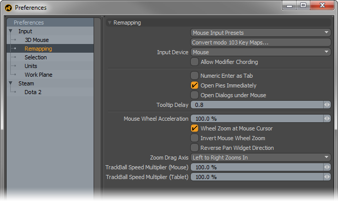
Remapping--
Mouse Input Presets: Users coming to MODO who are familiar with another 3D application might find themselves unable to switch into MODO mode. The 'Mouse Input Presets' are meant to adjust the mouse navigation controls to mimic those of the chosen application reducing users navigational stumbling, making it easier for switching back and forth between the other program. A variety of options are available representing a number of popular 3D programs.
Convert MODO 103 Key Maps: This legacy option converts MODO 103 keymaps to the current version. User would need to load v103 keymap configs using the 'Config Import' function found in the file menu prior to running this option.
Input Device: This option determines how MODO interprets input commands, users can choose either a 'Mouse' or 'Tablet' as the main form of input. Tablets typically use an absolute positioning based on a stylus' position on the tablet surface, whereas a Mouse uses a relative position based only on the initial position of the cursor. Users using a Tablet with relative positioning should set this option to 'Mouse'.
Allow Modifier Chording: When enabled, modifier keys can trigger 'Chording', when disabled, only mouse buttons can trigger chording. Chording is the use of multiple mouse buttons simultaneously. It should be noted that chording has been widely recognized as a key contributor to carpal tunnel syndrome and other repeated stress injuries. The Foundry recommends that users avoid chording to prevent unnecessary muscle strain.
Numeric Enter as Tab: When enabled, pressing the 'Enter' key on the numeric keypad will function the same way as pressing the Tab key does, by advancing the cursor to the next logical data field.
Open Pies Immediately: This option determines whether there is a slight delay to the opening of Pie Menus when disabled, or if the menus open immediately when enabled. For users not accustomed to Pie Menus, the delay may be helpful in eliminating menus from popping open unexpectedly on errant key presses.
Open Dialogs Under Mouse: This option forces new dialog boxes to always open at the current mouse position (such as the 'Save As' and 'Open' file dialogs). When disabled, dialog boxes will open in the same position as the last open dialog box.
Tooltip Delay: Defined in seconds, this option determines the length of time before the tooltip info display opens when hovering the mouse pointer over a button or function of MODO. The default value is 0.8 seconds.
Mouse Wheel Acceleration: This percentage value determines the speed at which MODO zooms in or out when using a mouse's scroll wheel. Higher values will zoom faster, while lower values will zoom more slowly.
Wheel Zoom at Mouse Cursor: When this option is enabled, zooming in any OpenGL viewport with the mouse scroll wheel will center the zoom based on the mouse's position over the viewport, when disabled, the mouse's position is disregarded and the viewport will zoom based on its center.
Invert Mouse Wheel Zoom: This option inverts the zooming behavior of the mouse wheel. Pushing forward on the wheel will push out instead of in.
Zoom Drag Axis: This option determines the directional behavior when hauling in a 3D viewport when zooming. The options are 'Left to Right', 'Right to Left', 'Bottom to Top' and 'Top to Bottom'.
Trackball Speed Multiplier: This option determines the rotation speed for using Trackball rotation when navigate in an OpenGL viewport. There are separate settings for both 'Mouse' and 'Tablets'.
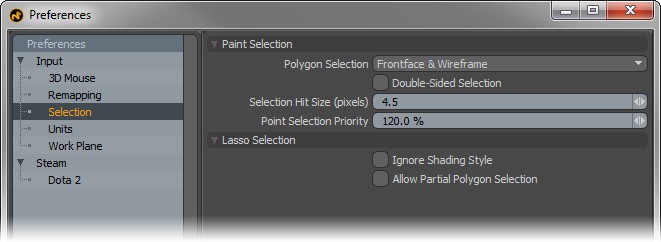
Paint Selection--
Polygon Selection: This option determines the behavior of lasso or paint selection modes when selecting components in the OpenGL viewports.
Frontface & Wireframe- Default behavior is only forward facing polygons are selected, except when in Wireframe mode where both the front and back facing polygons are selected.
Frontface & Backface-
Default behavior is front and back faces are always selected regardless of viewport style.
Frontface only- Default behavior is to select only front facing geometry regardless of viewport style.
Always Raycast- Paint selection does occlusion testing for hit element regardless of shading style. Wireframe view is treated as solid shading view. If the hit element is occluded by polygon on wireframe view, it is not selected.
No Raycast- Paint selection does NOT do occlusion testing for hit element regardless of shading style. Shaded view is treated as wireframe shading view. Even if the hit element is occluded by polygon on shaded view, it is not selected.
Double Sided Selection: When this option is enabled, any polygons tagged with a material that is defined as 'Double Sided', users can then paint select these polygons from their back side. When disabled, users are unable to paint select polygons from the back.
Selection Hit Size: This value determines the area around a selectable (pre-highlighted) element where clicking the mouse will select it. This value is determined as screen size pixel scale.
Point Selection Priority: This is for controlling the multi component selection mode used in tools such as 'Element Move'. When the cursor is close to the corner of polygon, the distances from the cursor to vertex and the connected edges are very close. The 'Point Selection Priority' option gives priority to point selection over edge selection.
Lasso Selection--
Ignore Shading Style: The typical behavior of polygon selection in MODO is to select what is visible to the user, this means that when marquee selecting a sphere in Shaded display style, only the polygons facing the users are selected, but while in Wireframe display style the same selection will select both forward and backward facing polygons (as the rear facing polygons are now visible to the user, therefore selectable). When 'Ignore Shading Style' is enabled MODO's selection mode will work identically regardless of the viewport display style.
Allow Partial Polygons Selection: In order to select a polygon when using the marquee selection style, users will need to completely surround the target with the marquee in order to successfully select the intended geometry. With the 'Allow Partial Polygons Selection' option enabled, all selectable geometry that is intersected by the marquee line, even by a tiny bit, will be selected.
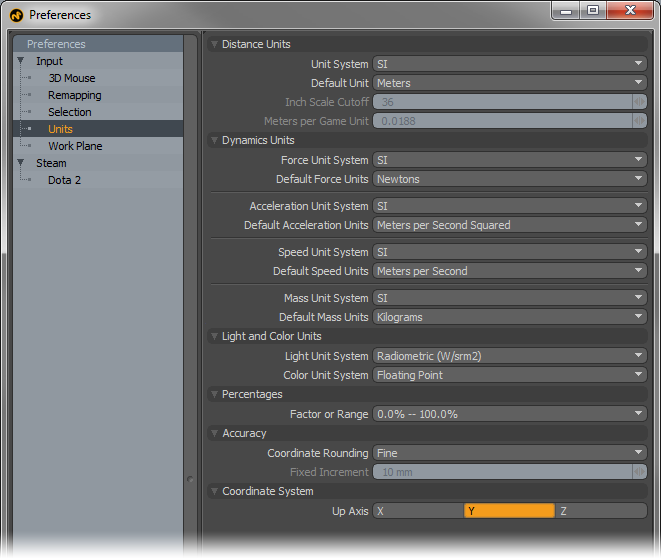
Distance Units--
Unit System: Users can choose their preferred measurement units system based on several options. Once set, this is the measurement input method MODO will use for all numerical input values-
SI- The International System of Measurement (abbreviated 'SI') is the modern form of Metric, complies to universal base units.
Metric- A universal system of measurement based on powers of '10' -millimeter, centimeter, meter, kilometer.
English- A historical measurement system based on Imperial Units -mils, inch, foot, yard and mile
Game Units- An arbitrary unit of measurement (defined by the 'Meters per Game Unit' setting).
Unitless- An arbitrary decimalized unit of measurement based on cubic meters, essentially 1 unit = 1m.
Default Unit: This option is dependent on the 'Unit System' and determines the default unit used when no unit is specified.
Inch Scale Cutoff: When the 'English' Unit System is selected, the 'Inch Scale Cutoff' determines the cutoff where MODO will display strictly inches as feet and inches. For example, when set to the default 36, 27 inches will display as 27", but 42 inches will display as 3' 6".
Meters per Game Unit: When utilizing the arbitrary 'Game Units' systems, users can use this value to determine the scale of a single unit. This allows users to work with even whole numbers. So if a 1m equivalent is really 1.375 real world meters in MODO, users an simply enter 1.375 here and then specify units normally in the numerical input fields.
Dynamic Units--
Force Unit System: This option determines the default Force unit MODO uses when specifying dynamic Force-
Default Force Units: Users can specify alternate units of Force to work with using this control. MODO will default to the selected unit when a unit is not specified in the related input field.
Acceleration Units System: This option determines the default Acceleration unit MODO uses when specifying acceleration-
Default Acceleration Units: Users can specify alternate units of Acceleration to work with using this control. MODO will default to the selected unit when a unit is not specified in the related input field.
Speed Unit System: This option determines the default Speed unit MODO uses when specifying speed (distance traveled over time)-
Default Speed Units: Users can specify alternate units of Speed to work with using this control. MODO will default to the selected unit when a unit is not specified in the related input field.
Mass Units System: This option determines the default unit of Mass MODO uses when specifying an objects Mass-
Default Mass Units: Users can specify alternate units of Mass to work with using this control. MODO will default to the selected unit when a unit is not specified in the related input field.
Light and Color Units--
Light Unit System: This option determines the default Light Unit MODO uses when specifying a lights brightness-
Radiometric- Measurement of the electromagnetic spectrum (which included visible light); defined by power of radiation.
Photometric-
Measurement of brightness of light as perceived by human eye; defined by luminous intensity.
Color Unit System: Determines the color unit system used for specifying colors in MODO-
Floating Point- Determines colors based on decimals, uses 0-1 range (and beyond for HDR colors).
Percentage- Determines colors based on percentages, uses 0%-100% range.
Integer- Determines colors based on 8bit value scale, uses 0-255 range (2 to 8th power = 256 values)
Hexadecimal- A computer numerical system similar to binary represented by 16 characters. 2bit Hex produces 256 values, similar to Integer color units. Widely used in specifying color on the web, uses 00.00.00-ff.ff.ff range.
Percentages--
Factor or Range: This option determines surfacing and material value units, users can specify values as a percentage 0%-100% or as a float value 0.0-1.0
Accuracy--
Coordinate Rounding: This option controls how mouse input is converted, via the Work Plane, into 3D coordinates.
None-- This means that no coordinate rounding is done. Every mouse move gives unclamped coordinates (typically with lots of decimals). This option is basically the raw 2D -> 3D transform. Useful for working freehand.
Normal-- This option attempts to give clean, round coordinates based on the users view transform; so as the mouse moves, users can see values that are nice in your current unit system display in the information tab. The step size will get smaller or larger as the user zooms in or out. Users may need to move the mouse cursor 2-3 pixels to see values update.
Fine-- This option is similar to 'Normal' but optimizes for closer to one step of coordinate rounding from one pixel of mouse movement. Gives the user finer grained input, but can be difficult to hit exact values.
Fixed-- This option uses the 'Fixed Increment' preference to put a lower limit on both coordinate rounding and the grid. If the user sets the fixed increment to 10mm that means the grid will never get finer than 10mm, and all input will be rounded to the nearest 10mm even at high zoom. When zoomed out, however, the grid will show larger values but the step size will always be a multiple of the fixed increment.
Forced Fixed-- This option is similar to 'Fixed', but forces the size of the grid and the input step to match the increment exactly no matter the zoom level.
Fixed Increment: When the Coordinate Rounding is set to either 'Fixed' options, this value determines the Fixed coordinate rounding grid.
Coordinate System--
Up Axis: This option determines the major axis that is considered the default up direction for MODO. 3D programs typically use 'Y' as up, where CAD applications typically use 'Z' as the up direction. When importing geometry, if it is always 90° off, changing the up axis to match the originating application may resolve the issue. This can also be set on a per scene basis in the 'Scene Item'.
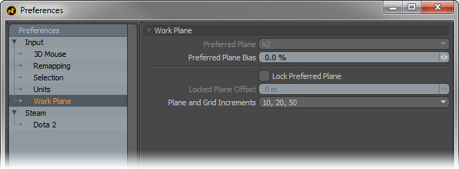
Work Plane--
Users can favor certain planes when using the Work Plane, especially in instances where users don't want to lock the plane, but it would be helpful to have it face a certain direction, such as modeling a rough city, users could rotate the views but keep the Work Plane mostly facing upwards (like it was the ground) when creating new geometry.
Preferred Plane: When the 'Preferred Plane Bias option is set above 0%, uses can choose a preferred Work Plane. Based on the bias amount, MODO will attempt to keep the work plane positioned at the preferred plane determined by its two major axes.
Preferred Plane Bias: When working with the Work Plane, MODO tries to keep the plane perpendicular to the viewport window when navigating and rotating the view. Increasing the Plane Bias option will increase MODO's favor of the Preferred Plane. Setting a very high value means MODO would almost always favor the preferred plane.
Lock Preferred Plane: Users may also prefer to lock the Work Plane to a specific plane facing direction by enabling this option. Once fixed, rotating the viewport will have no effect on the position or angle of the work plane.
Locked Plane Offset: When the Work Plane is locked, users can additionally set an offset (from the origin), providing accurate control over the position and placement of the work plane when used as a construction plane.
Plane and Grid Increments: As users zoom in and out of a scene, the Work Plane grid adjusts the density of the grid divisions adding or removing subdivisions based on the Plane Increments. Users can modify this behavior using this option.
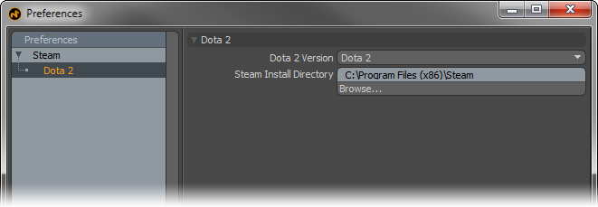
Dota 2--
Dota 2 Version: Determines the version of Dota to export.
Steam Install Directory: Defines the location of where Steam is installed.
Top